Monitoring system and imaging system

a technology of imaging system and monitoring system, which is applied in the field of monitoring system, can solve the problems of insufficient recognition of the face of a criminal recorded on the vtr, inability to obtain images by imaging devices such as ccd cameras, and long search tim

Inactive Publication Date: 2002-02-07
GK BRIDGE 1
View PDF0 Cites 111 Cited by
  • Summary
  • Abstract
  • Description
  • Claims
  • Application Information

AI Technical Summary

Benefits of technology

[0013] An object of the present invention is to provide a monitoring device capable of easily recording a face image important to specify an individual.
[0017] An object of the present invention is to provide a monitoring device capable of easily doing monitoring even in the place where there is no illuminance, for example, in the night.

Problems solved by technology

In cases such as a case where a crime occurred, the face of a criminal recorded on the VTR cannot, in some cases, be sufficiently recognized.
Even in a case where almost all of persons are absent, for example, in the night, recording is always made on the VTR, so that a huge amount of a video tape or the like is required, and it takes long to make a search at a later time.
[3] In the place where there is no predetermined illuminance, for example, in the night, an image cannot be obtained by an imaging device such as a CCD camera.
Therefore, the imaging device cannot be used as a monitoring camera for prevention.
In order to judge whether or not the image is a person, an operator must make the judgment by observing the monitor or the like, resulting in band operability.

Method used


Image

  • Monitoring system and imaging system
  • Monitoring system and imaging system
  • Monitoring system and imaging system

Examples


Embodiment Construction

[0065] Embodiments of the present invention will be described while referring to the drawings.

[0066] [1] Description of First Monitoring System

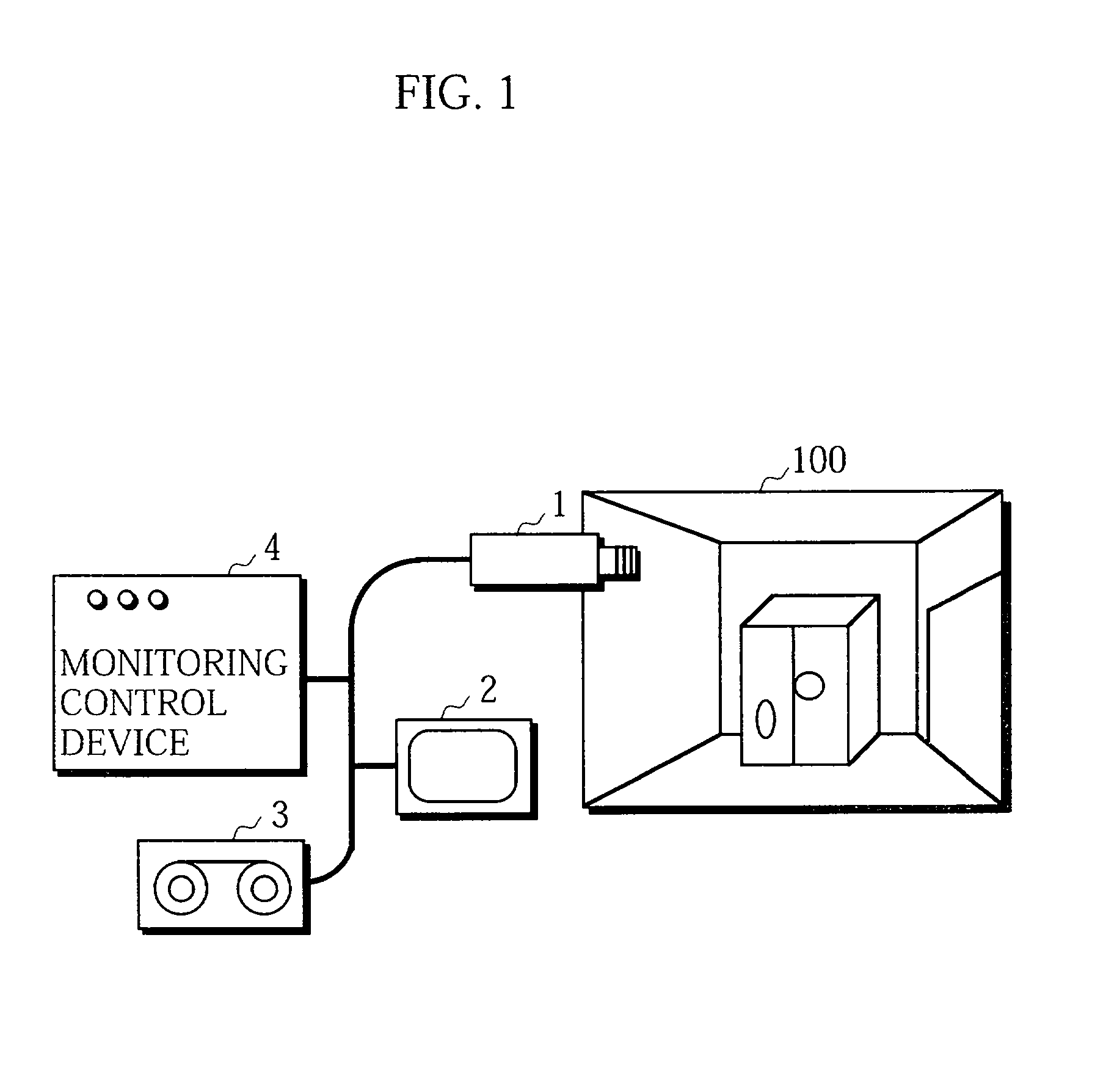
[0067] FIG. 1 illustrates the schematic configuration of a first monitoring system capable of detecting that a person enters a monitoring area from an area outside the monitoring area.

[0068] The first monitoring system comprises a video camera 1 for imaging a monitoring area 100, a monitor 2 for displaying an image picked up by the video camera 1, a recording device 3 for recording the image picked up by the video camera 1, and a monitoring control device 4.

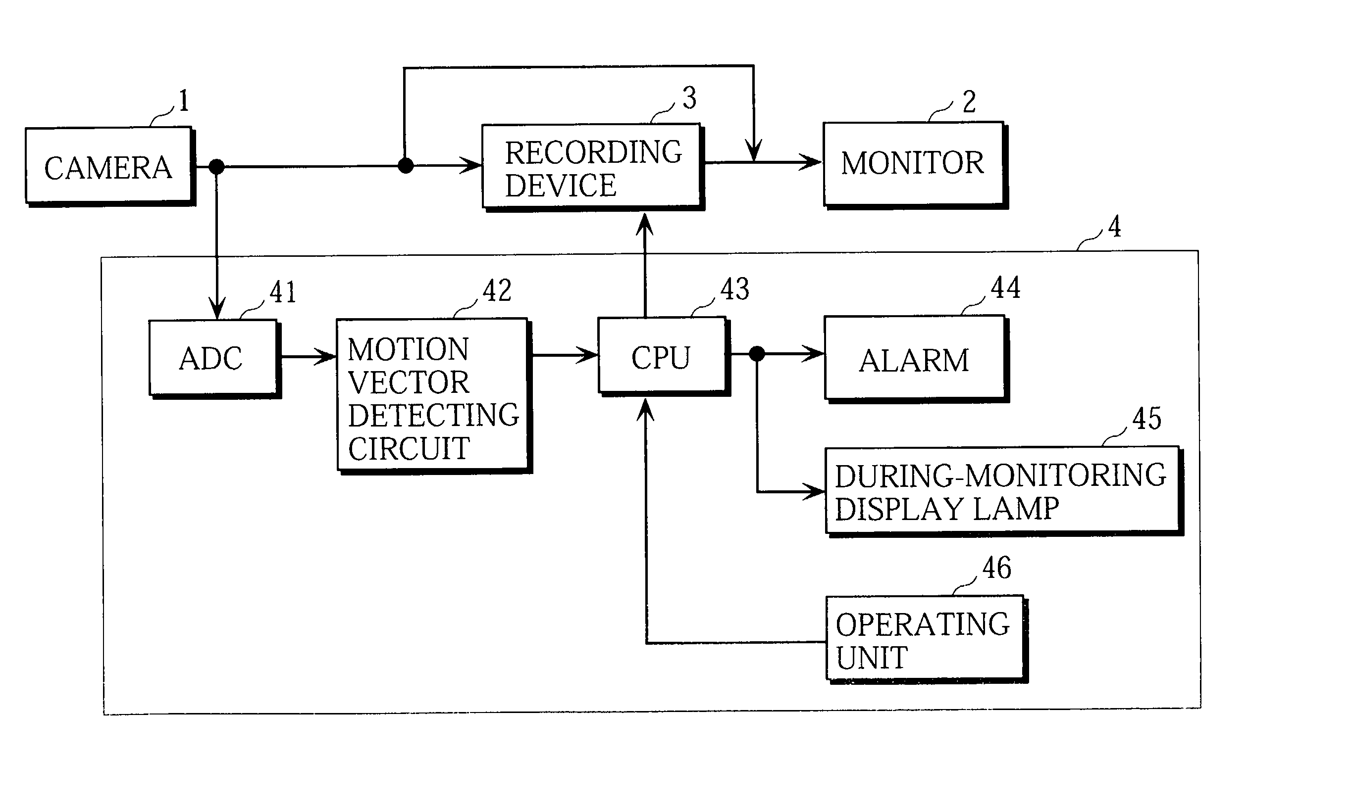
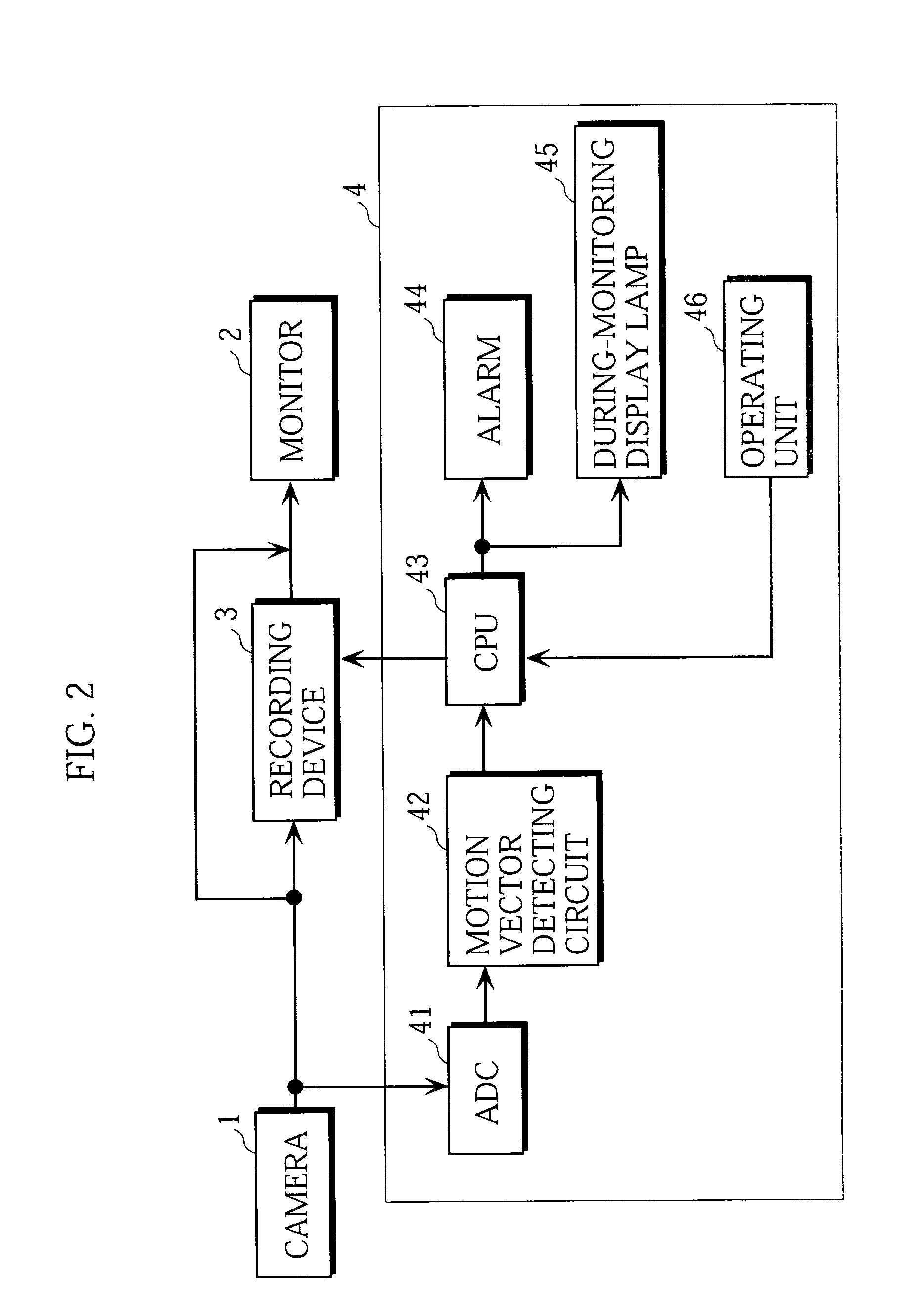
[0069] FIG. 2 illustrates the electrical configuration of the first monitoring system.

[0070] An output of the video camera 1 is fed to the monitor 2, the recording device 3, and the monitoring control device 4. The image picked up by the video camera 1 is always displayed on the monitor 2. The recording device 3 is controlled on the basis of a control signal from the monitoring control dev...


PUM


Abstract

The present invention relates to a monitoring system capable of automatically detecting and reporting to a supervisor that a person enters a monitoring area from an area outside the monitoring area. The present invention comprises an imaging device for imaging the monitoring area, and means for detecting information relating to the movement of an object in the monitoring area.

Description

BACKGOUND OF THE INVENTION[0001] 1. Field of the Invention[0002] The present invention relates to a monitoring system capable of detecting that a person enters a monitoring area from an area outside the monitoring area, or a person exists from the monitoring area to the area outside the monitoring area.[0003] The present invention relates to a monitoring device capable of imaging a characteristic part such as the face of an entering person.[0004] The present invention relates to a monitoring device capable of monitoring a place which cannot be monitored by an imaging device such as a CCD (Charge Coupled Device) camera in the night, for example.[0005] The present invention relates to an imaging system for intermittently recording a picked-up image of a subject .[0006] 2. Description of the Prior Art[0007] [1] An example of a conventional monitoring system for prevention is one for always imaging a monitoring area using a video camera, and displaying a picked-up image on a monitor as ...

Claims


Application Information

Patent Timeline
Patent Type & Authority Applications(United States)
IPC IPC(8): G08B13/194
CPCG08B13/19602G08B13/19643G08B13/19652G08B13/19697
Inventor KUWANO, YUKINORIOKINO, TOSHIYUKIIKEDA, TAKASHIARISAWA, MASATOFUJITA, HIDETOMURATA, HARUHIKO
Owner GK BRIDGE 1
Why Eureka
Try Eureka