
Electronic illuminated house sign

a technology for electronic illumination and house numbers, applied in the direction of illuminated signs, display means, instruments, etc., can solve the problems of high purchase price, high maintenance and replacement cost, and devices that do not provide a numbering visible during the day

Inactive Publication Date: 2002-02-14
WEISS RICHARD S
View PDF0 Cites 43 Cited by
  • Summary
  • Abstract
  • Description
  • Claims
  • Application Information

AI Technical Summary

Benefits of technology

[0025] In accordance with an eleventh aspect of the invention, the diffuser has a whitish color, so that the cutouts in the stencils are easily visible during daylight hours, when the illuminatable panel is not illuminated.

Problems solved by technology

Devices such as the one described above suffer from a common shortcoming however: complexity, resulting in high purchase price, and high maintenance and replacement cost.
Furthermore, many of these devices do not provide a numbering visible during the day, since the typical illuminated characters chosen do not provide a display which is easily discernable during daylight hours.
This invention has the disadvantage of using solar energy to power the battery and the disadvantage of increased cost.
Also it is associated with a mailbox and not necessarily useful in other location such as inside buildings.
One of the problems not addressed by other lighted house signs is that they do not show up well during daylight hours, even when illuminated.
Flimsy materials such as cardboard, and corroding materials, such as iron, are not suitable for this application, since the sign will be outside, exposed to rain, snow, sunlight, and other such weather conditions.
Thus normally much of the energy is wasted in the series resistor that is used to maintain constant current through the LED.
There are a variety of semiconductor circuits which can provide the constant current required by the LEDs without the power loss of the dropping resistor approach, but this increases the cost of the device,

Method used


Image

  • Electronic illuminated house sign
  • Electronic illuminated house sign
  • Electronic illuminated house sign

Examples


Embodiment Construction

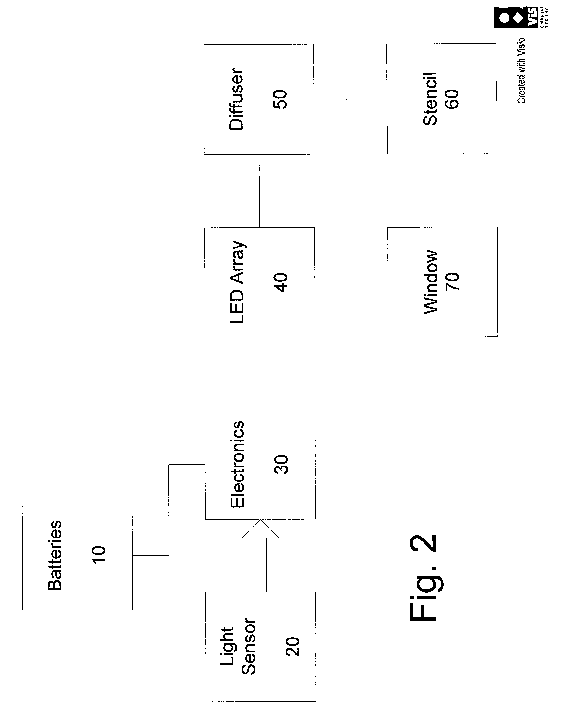
[0076] Referring now to FIG. 2, a block diagram of the device is depicted. Batteries 10 provide continuous standby current at very low levels to a light sensor 20 that is monitored by a low power CMOS threshold circuit, which is part of the electronics 30. The battery(s) 10 also continuously powers the threshold portion of the electronics. The standby current is in the microampere range and only reduces the battery energy and life by a very small amount. When the threshold circuit detects that the light on the light sensor falls below a preset value, the threshold circuit activates power to the rest of the electronics, which energizes the LED array 40. The light from the array passes through a diffuser 50, which makes the light source appear more uniform. The light from the diffuser 50 passes through a stencil 60 that forms numbers, and / or letters in the transmitted light. The light then passes through a transparent window 70 that is used to protect the interior from the weather.

[00...


PUM


Abstract

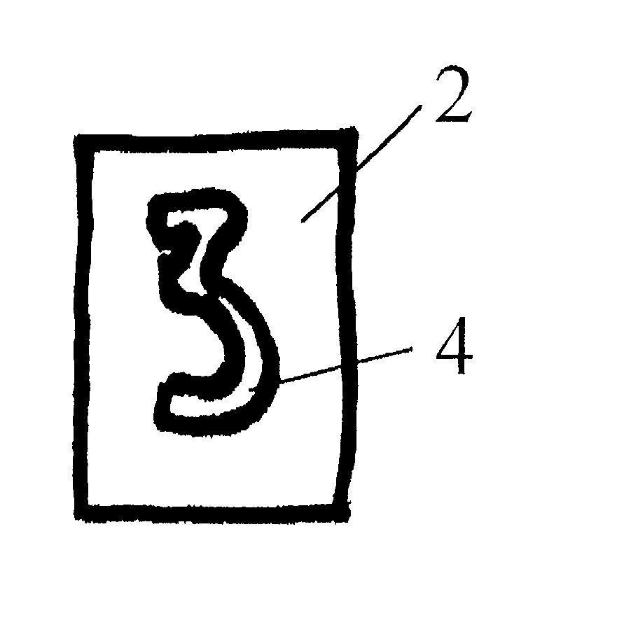
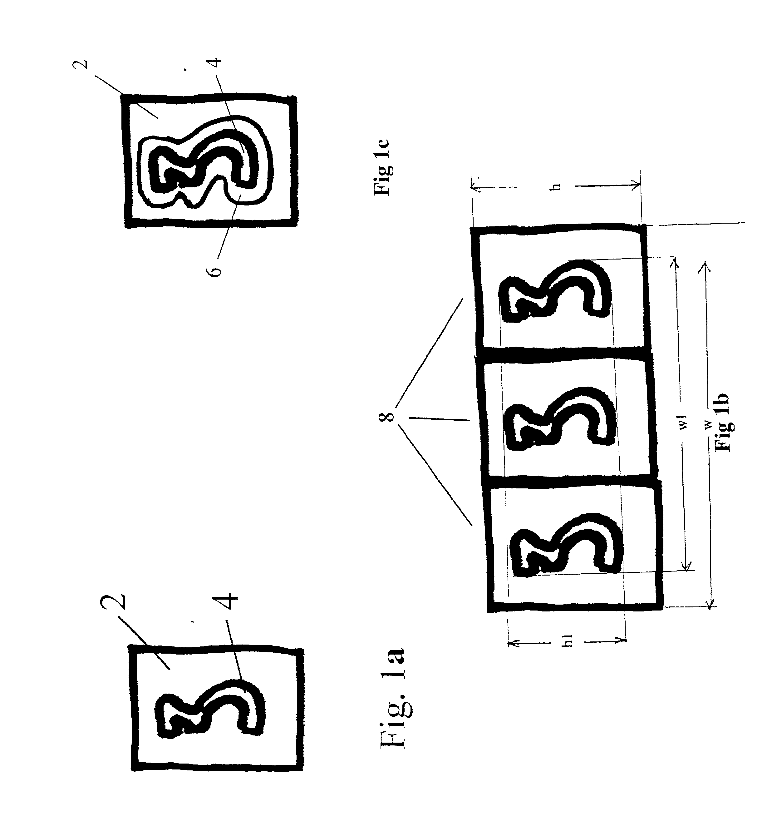
An illuminated sign, readable during the night or day, and suitable for use as a house number display, uses a single illuminatable panel, on which a number of stencils are plac critical flicker frequency ed. Each stencil is a rectangular piece of opaque material, such as plastic or metal, in which a central cutout is made in the shape of a number. Several of these stencils are arrayed in front of the illuminatable panel, so that only the light coming through the central cutouts is visible through the stencils. The illuminatable panel is made of an array of LED's, with a diffuser to produce a uniform illumination, and is powered by one or more batteries. A light detector senses the onset of dusk, which activates the illuminatable panel, turning it on, and leaving it on for four or more hours. A constant-current electronic system powers the LEDs, which are pulsed on and off at a speed greater than 90 Hz, which makes the sign appear to the human eye as constantly illuminated. A timer leaves the illuminatable panel illuminated only for a few hours, in order to maximize the life of the batteries.

Description

[0001] This application is a continuation in part of Ser. No. 09 / 632,237, filed on Aug. 3, 2000, which is incorporated herein by reference.[0002] 1. Field of the Invention[0003] The present invention relates to a device for visually indicating house numbers during both daylight hours and at night. More specifically, this invention relates to such a device which provides an easy modification for different numbers, and is battery operated but causing a low power drain.[0004] 2. Description Relative to the Prior Art[0005] Illuminated house numbering devices are well known, and there is much prior art describing such systems. Typical of these is U.S. Pat. No. 5,007,190, which provides a programmable system which is solar powered, thus allowing the device to be installed without connection to the internal wiring system of the house. The solar cells of this prior art device are used to charge an internal battery during the day, and the battery powers the device at night.[0006] Devices suc...

Claims


Application Information

Patent Timeline
IPC IPC(8): G09F13/04
CPCG09F13/04G09F13/0409
Inventor WEISS, RICHARD S.ECKHARDT, RICHARDAISENBERG, SOL
Owner WEISS RICHARD S
Learn More