Flash unit

a flash unit and flash technology, applied in the field of flash devices, can solve the problems of increasing the cost of the flash circuit, wasting batteries, and requiring a lot of space for conventional autostop flash circuits

Inactive Publication Date: 2002-02-14
FUJIFILM CORP
View PDF0 Cites 6 Cited by
  • Summary
  • Abstract
  • Description
  • Claims
  • Application Information

AI Technical Summary

Benefits of technology

[0012] A further object of the present invention is to provide a flash device which is effective to prevent the photographer from forgetting to turn off the flash charge switch, and is also suitable especially for use in a lens-fitted photo film unit.
[0015] The flash device according to the invention makes it possible to use an inexpensive Zener diode with a low Zener voltage, so that it is possible to cut the cost of the flash device.
[0016] By charging a stopping capacitor with the Zener current that flows when the main capacitor reaches the set charge voltage and then applying current discharged from the stopping capacitor to the stopping transistor through a resistor, the stopping transistor keeps operating for a predetermined time. It ensures stopping charging the main capacitor, and also prevents unexpected interruption of charging that may be caused by noises.
[0019] As the indication device for indicating the completion of charging the flash circuit protrudes outside when the flash charge switch is turned on, it is easy to check if the flash charge switch is in the ON state or not. Accordingly, the present invention is effective to remind the photographer to turn off the charge switch when the flash circuit needs not charging. Thus, the flash device of the present invention solves the above described problem of wasting the battery and making the flash device useless for the following photography.

Problems solved by technology

As the Zener diode with high Zener voltage is expensive, it raises the cost of the flash circuit.
In addition, the conventional autostop flash circuit requires a lot of space for mounting various elements as above which are necessary for the automatic continuation and stopping of charging.
If the operation device is left in the charging position after the photography is terminated, the battery is wasted.
As a result, the battery runs down and it becomes impossible to use the flash device before all of the available exposures are carried out.
However, according to the configurations of the conventional lens-fitted photo film units, it is not easy to know the switching condition of the operation member at a glance, or the charge condition indicating light is not visible from the outside of the lens-fitted photo film unit.
Therefore, the photographer can fail to reset the charge switch to the OFF position.

Method used


Image

  • Flash unit
  • Flash unit
  • Flash unit

Examples


Embodiment Construction

[0044] The present invention will be described in more detail with reference to the accompanying drawings.

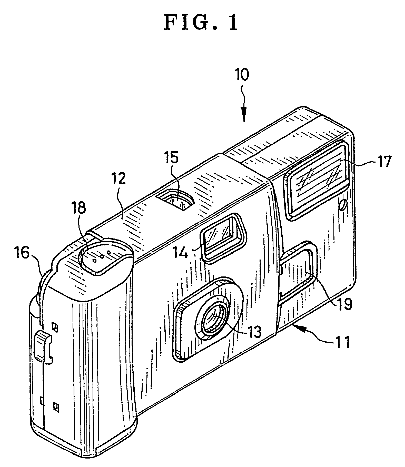
[0045] Referring to FIG. 1, a lens-fitted photo film unit 10, hereinafter referred to as a film unit, has a unit body 11 containing a photo filmstrip. A simple photographic mechanism and a flash device are incorporated into the unit body 11. A decorative cardboard paper 12 is wrapped around the unit body 11. A taking lens 13, a finder objective window 14, a frame counter window 15, a film winding wheel 16, a flash projector 17, a shutter button 18, a charging operation member or charge button 19 and other necessary elements are exposed to the outside through openings of the cardboard paper 12 or located out of the cardboard paper 12. An indication window for indicating that the flash device is ready to flash is formed besides a viewfinder eyepiece, through they are not shown in the drawings.

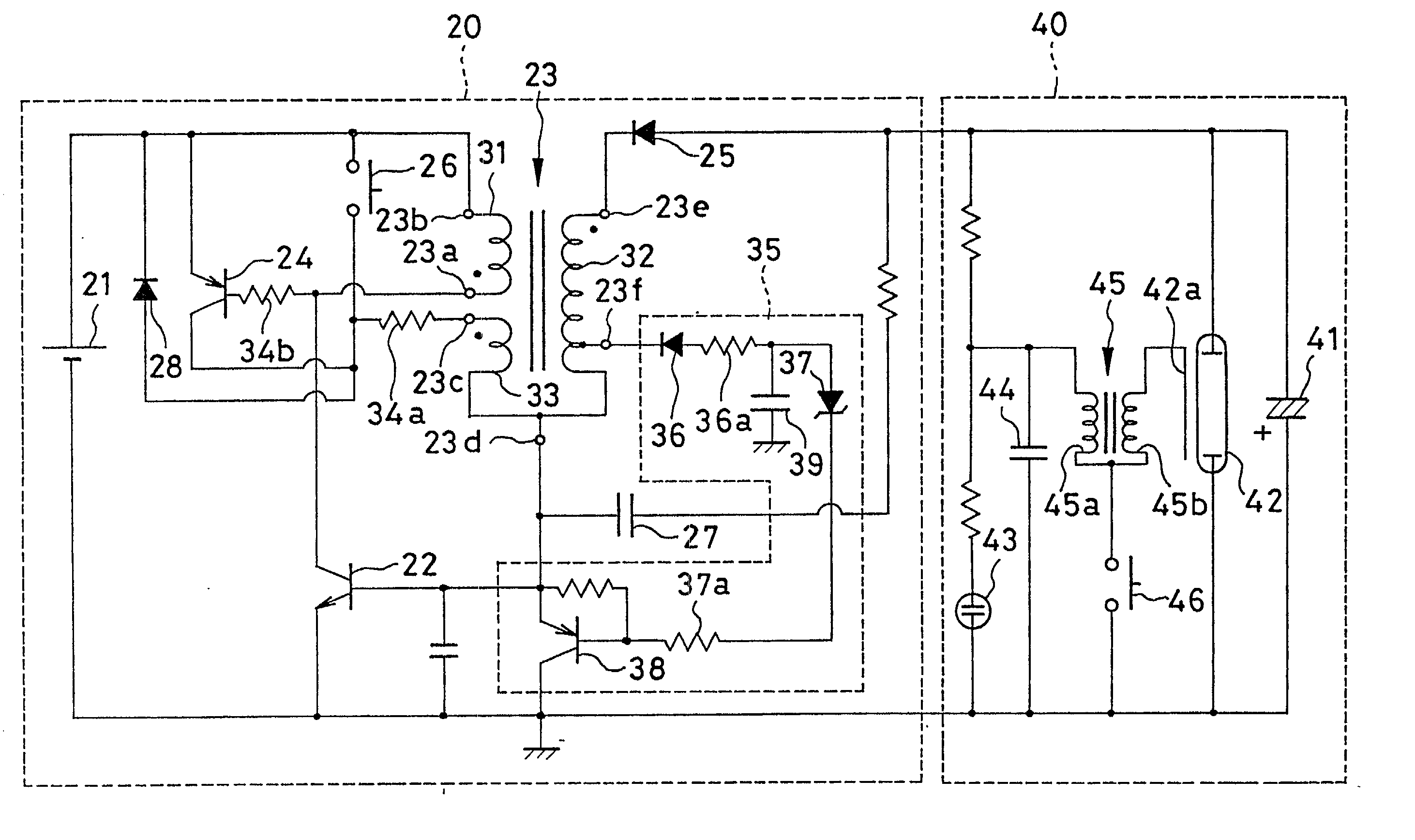
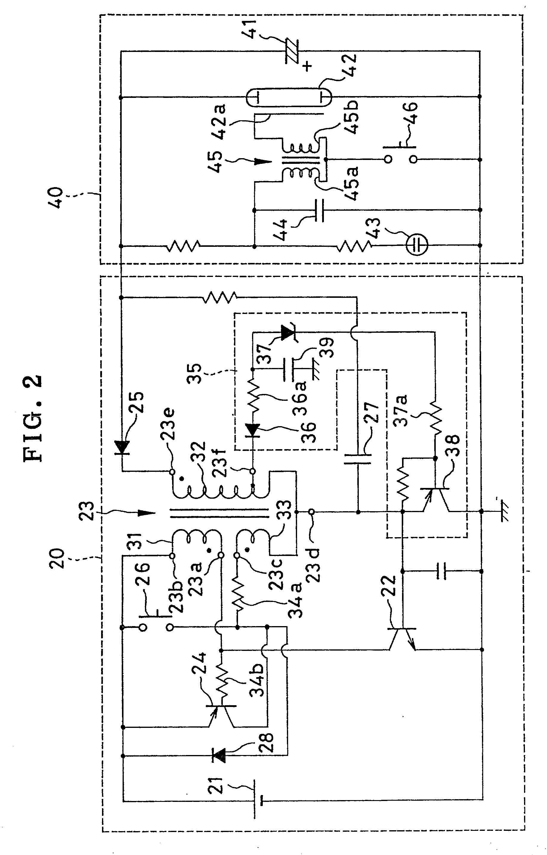
[0046] Referring to FIG. 2 showing a flash circuit of the flash device, a flash charge sw...


PUM


Abstract

In a flash circuit of a flash device, a Zener diode (37) is connected to a tap point (23f) located at an intermediate position of a secondary coil of an oscillation transformer (23). The oscillation transformer (23) and an oscillation transistor (22) constitutes an oscillation circuit. A potential at the tap point (23f) changes proportionally to a voltage charged in a main capacitor (41). When the main capacitor (41) is charged up to a set voltage, the Zener diode (37) conducts a Zener current, which activates a stopping transistor (38) and thus deactivates the oscillation circuit. When a flash charge switch (51) is turned on, an end of a light guide portion of a charge condition indicator (60) protrudes out of a lens-fitted film unit. When the main capacitor (41) is charged up to the set voltage, a light emission element starts lighting, and the light from the light emission element is projected from the end of the light guide portion.

Description

FIELD OF THE ART[0001] The present invention relates to a flash device, and more particularly to a flash device which is suitable for being incorporated in a lens-fitted photo film unit that contains a roll of photo filmstrip and is provided with a simple photographic mechanism including a taking lens.BACKGROUND ARTS[0002] When the subject brightness is so low that a proper exposure would not be provided without any artificial illumination, a flash device is often used to project light toward the subject synchronously with the shutter release. Since compact cameras and lens-fitted photo film units have an inexpensive lens system of a relative large f-number, most of them are provided with a built-in flash device. To make a flash photography, it is necessary to charge the main capacitor up to the set voltage prior to the shutter release. The conventional flash devices start charging in response to an actuation of a flash, charge switch.[0003] A flash circuit has recently been known, ...

Claims


Application Information

Patent Timeline
Patent Type & Authority Applications(United States)
IPC IPC(8): G03B7/16G03B15/05H05B41/32
CPCG03B7/16G03B15/05H05B41/32G03B2215/0503
Inventor ISOZAKI, MAKOTOTAKAGI, JUNICHIKOIKE, KAZUMIMORIYA, MITSUHIROUCHIYAMA, KEIJIHATA, YUKITSUGU
Owner FUJIFILM CORP
Why Eureka
Try Eureka