Methods and apparatus for calibrating CT x-ray beam tracking loop

a technology of x-ray beam and tracking loop, which is applied in the field of computed tomography (ct) imaging, can solve problems such as image artifacts, and achieve the effect of improving tracking calibration

Inactive Publication Date: 2002-02-21
GENERAL ELECTRIC CO
View PDF0 Cites 15 Cited by
  • Summary
  • Abstract
  • Description
  • Claims
  • Application Information

AI Technical Summary

Benefits of technology

0006] The above described system provides improved tracking calibration for CT imaging systems utilizing z-axis tracking loops for positioning x-ray beams.

Problems solved by technology

In a multi-slice system, movement of an x-ray beam penumbra over detector elements having dissimilar response functions can cause signal changes resulting in image artifacts.

Method used


Image

  • Methods and apparatus for calibrating CT x-ray beam tracking loop
  • Methods and apparatus for calibrating CT x-ray beam tracking loop
  • Methods and apparatus for calibrating CT x-ray beam tracking loop

Examples


Embodiment Construction

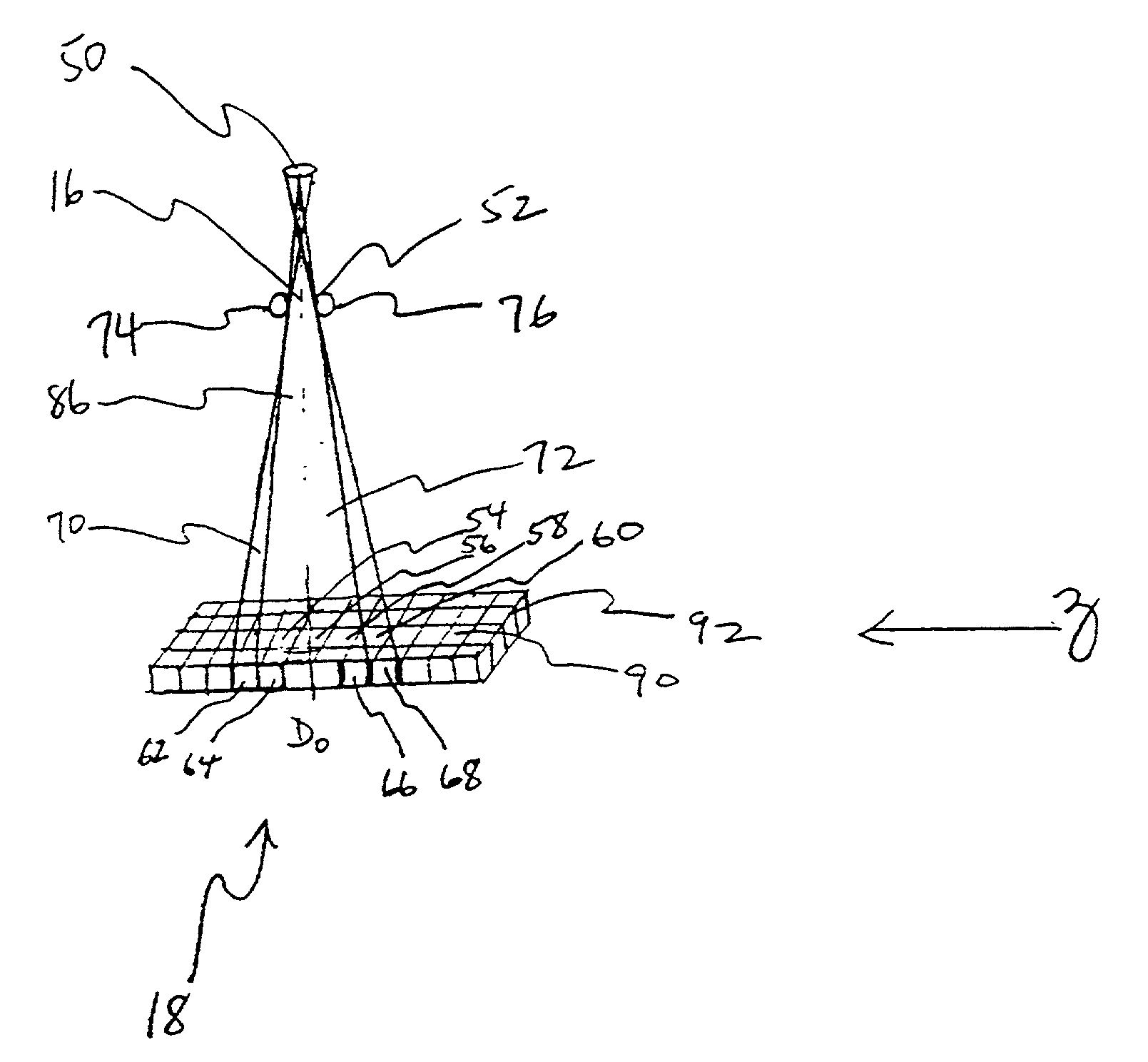
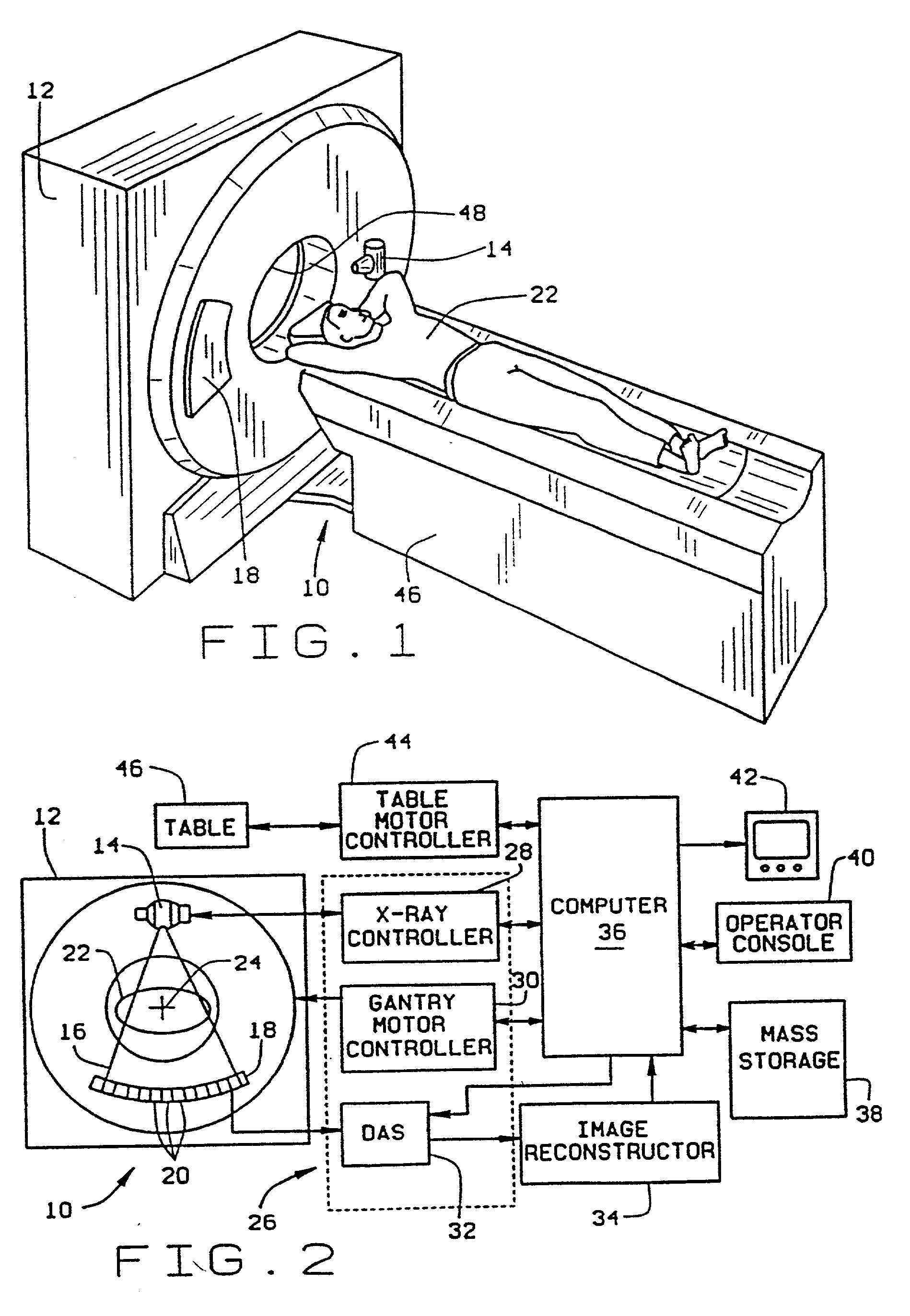
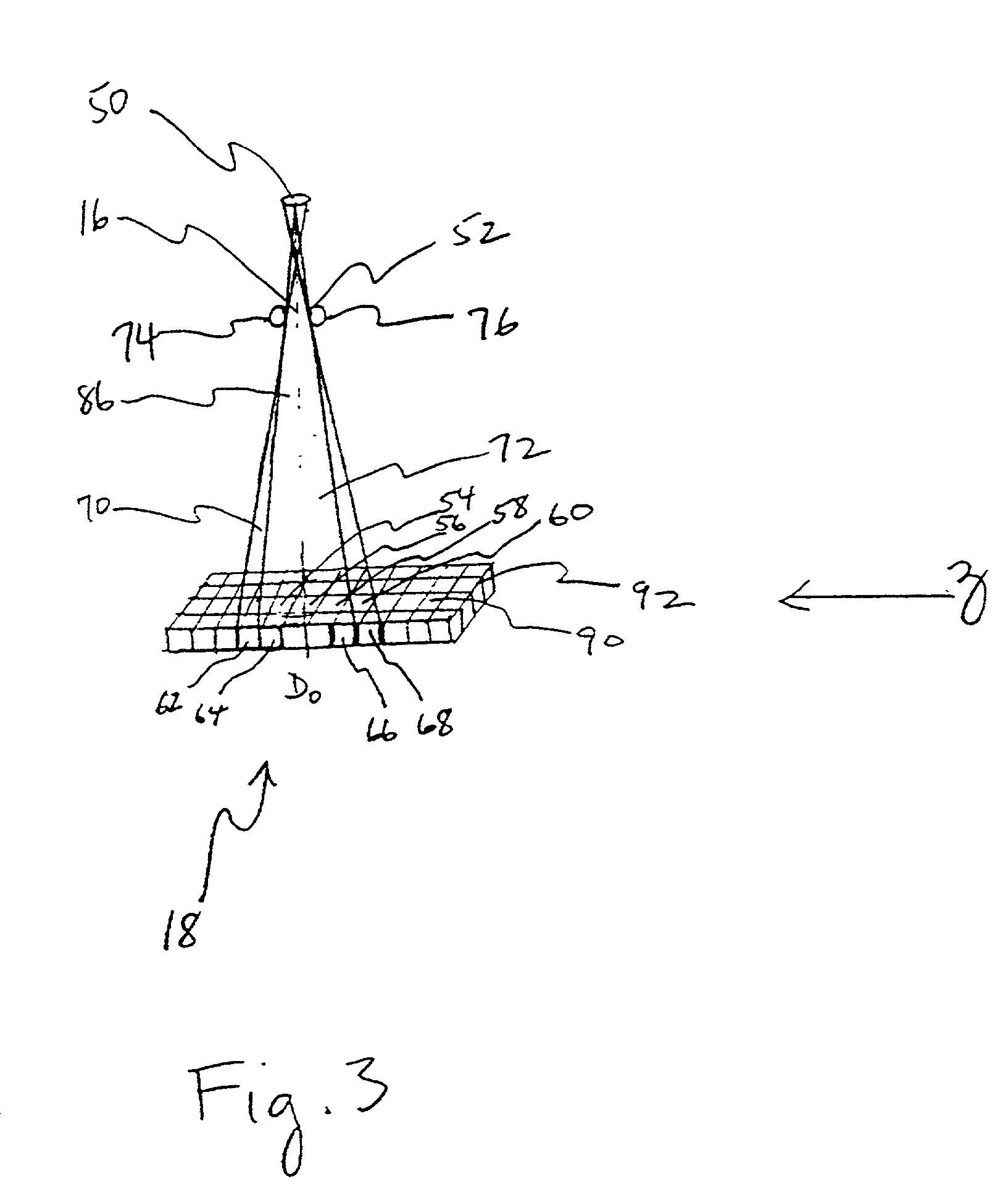
[0012] Referring to FIGS. 1 and 2, a computed tomograph (CT) imaging system 10 is shown as including a gantry 12 representative of a "third generation" CT scanner. Gantry 12 has an x-ray source 14 that projects a beam of x-rays 16 toward a detector array 18 on the opposite side of gantry 12. Detector array 18 is formed by detector elements 20 that together sense the projected x-rays that pass through an object 22, for example a medical patient. Each detector element 20 produces an electrical signal that represents the intensity of an impinging x-ray beam and hence the attenuation of the beam as it passes through patient 22. During a scan to acquire x-ray projection data, gantry 12 and the components mounted thereon rotate about a center of rotation or isocenter 24.

[0013] Rotation of gantry 12 and the operation of x-ray source 14 are governed by a control mechanism 26 of CT system 10. Control mechanism 26 includes an x-ray controller 28 that provides power and timing signals to x-ray...


PUM

PropertyMeasurementUnit
frequencyaaaaaaaaaa
frequencyaaaaaaaaaa
spot lengthaaaaaaaaaa

Abstract

The present invention is, in one embodiment, a method for determining tracking control parameters for positioning an x-ray beam of a computed tomography imaging system having a movable collimator positionable in steps and a detector array including a plurality of rows of detector elements. The method includes steps of obtaining detector samples at a series of collimator step positions while determining a position of a focal spot of the x-ray beam; determining a beam position for each detector element at each collimator step utilizing the determined focal spot positions, a nominal focal spot length, and geometric parameters of the x-ray beam, collimator, and detector array; and determining a calibration parameter utilizing information so obtained. For example, in determining a target beam position at which to maintain the x-ray beam, a detector element differential error is determined according to ratios of successive collimator step positions; and a target beam position is selected for an isocenter element in accordance with the determined element differential errors.

Description

BACKGROUND OF THE INVENTION[0001] This invention relates generally to computed tomography (CT) imaging and, more particularly, to methods and apparatus for calibration of z-axis tracking loops for positioning a CT x-ray beam of a multi-slice CT imaging system.[0002] In at least one known computed tomography (CT) imaging system configuration, an x-ray source projects a fan-shaped beam which is collimated to lie within an X-Y plane of a Cartesian coordinate system and generally referred to as the "imaging plane". The x-ray beam passes through the object being imaged, such as a patient. The beam, after being attenuated by the object, impinges upon an array of radiation detectors. The intensity of the attenuated beam radiation received at the detector array is dependent upon the attenuation of the x-ray beam by the object. Each detector element of the array produces a separate electrical signal that is a measurement of the beam attenuation at the detector location. The attenuation measu...

Claims


Application Information

Patent Timeline
Patent Type & Authority Applications(United States)
IPC IPC(8): G01N23/04A61B6/03
CPCA61B6/583G01N23/046G01N2223/612G01N2223/419A61B6/4021
Inventor TOTH, THOMAS L.SEIDENSCHNUR, GEORGE E.BROMBERG, NEIL B.
Owner GENERAL ELECTRIC CO
Why Eureka
Try Eureka