System and method for CT scanning of baggage

a ct scanning and baggage technology, applied in the field of computed tomography (ct) systems, can solve the problems of inconsistencies in real scans, and achieve the effect of enhancing analysis and avoiding clutter or shielding

Inactive Publication Date: 2006-05-16
REVEAL IMAGING TECH
View PDF22 Cites 82 Cited by
  • Summary
  • Abstract
  • Description
  • Claims
  • Application Information

AI Technical Summary

Benefits of technology

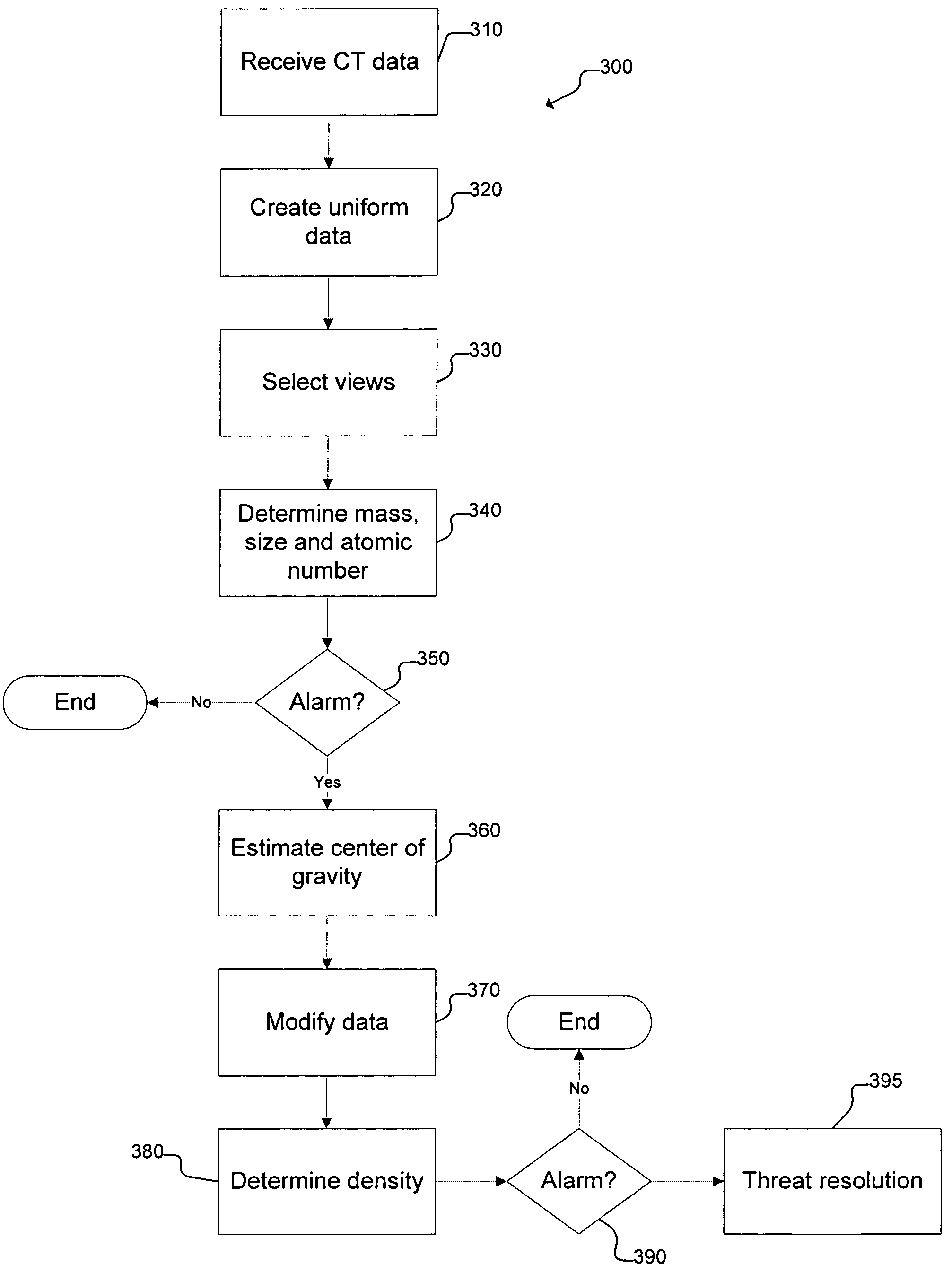
[0011]The deficiencies of the prior art are substantially overcome by the CT system and method of the present invention which conducts an analysis of the unreconstructed scanning data to locate potential threats. With the CT scan of the present invention, objects in a bag appear in the scanned data as sinusoidal representations of similar density or atomic number. The sinusoidal representations are analyzed to determine potential threats based upon data representing mass, size, atomic number and density. The size is estimated from the width and length of the sinusoidal representation of the object. According to another aspect of the invention, the density, mass or atomic number of an object is determined based upon a small portion of the data related to that object. The small portion of the object may be selected to avoid clutter or shielding from other objects.
[0013]According to another embodiment of the invention, a partial image reconstruction of the CT data is created. The CT image is reconstructed around a target area of the image based upon the information obtained from analysis of the sine wave data. The CT image may be reconstructed based upon the original data or upon data adjusted to approach an ideal sine wave. Furthermore, the target area may be determined based upon an analysis of various sine waves of objects in order to avoid clutter or shielding.
[0014]According to another aspect of the invention, baggage is analyzed while it is being scanned. When a potential threat is determined, the rate of the conveyor is slowed or stopped to allow additional data collection for enhanced analysis. Once the object has been properly analyzed, the conveyor may return to normal speed.

Problems solved by technology

Real scans, however, have various inconsistencies.
These inconsistencies may be the result of inherent inaccuracies in assumptions or upon unanticipated movement.

Method used


Image

  • System and method for CT scanning of baggage
  • System and method for CT scanning of baggage
  • System and method for CT scanning of baggage

Examples


Embodiment Construction

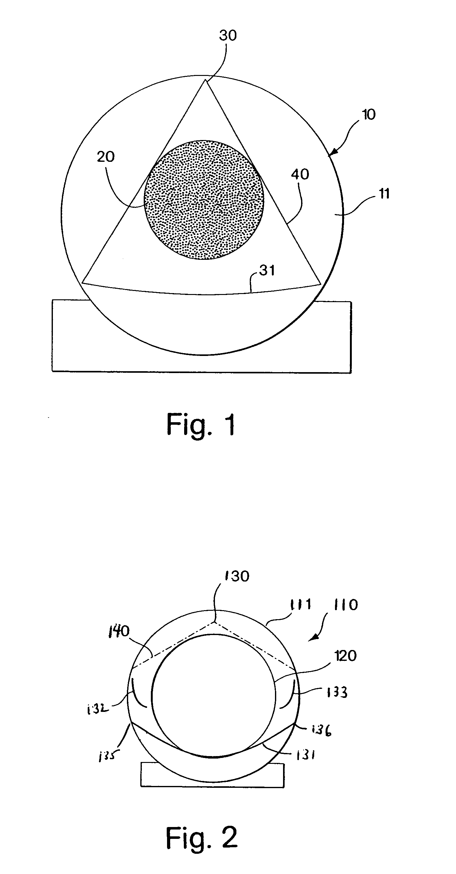
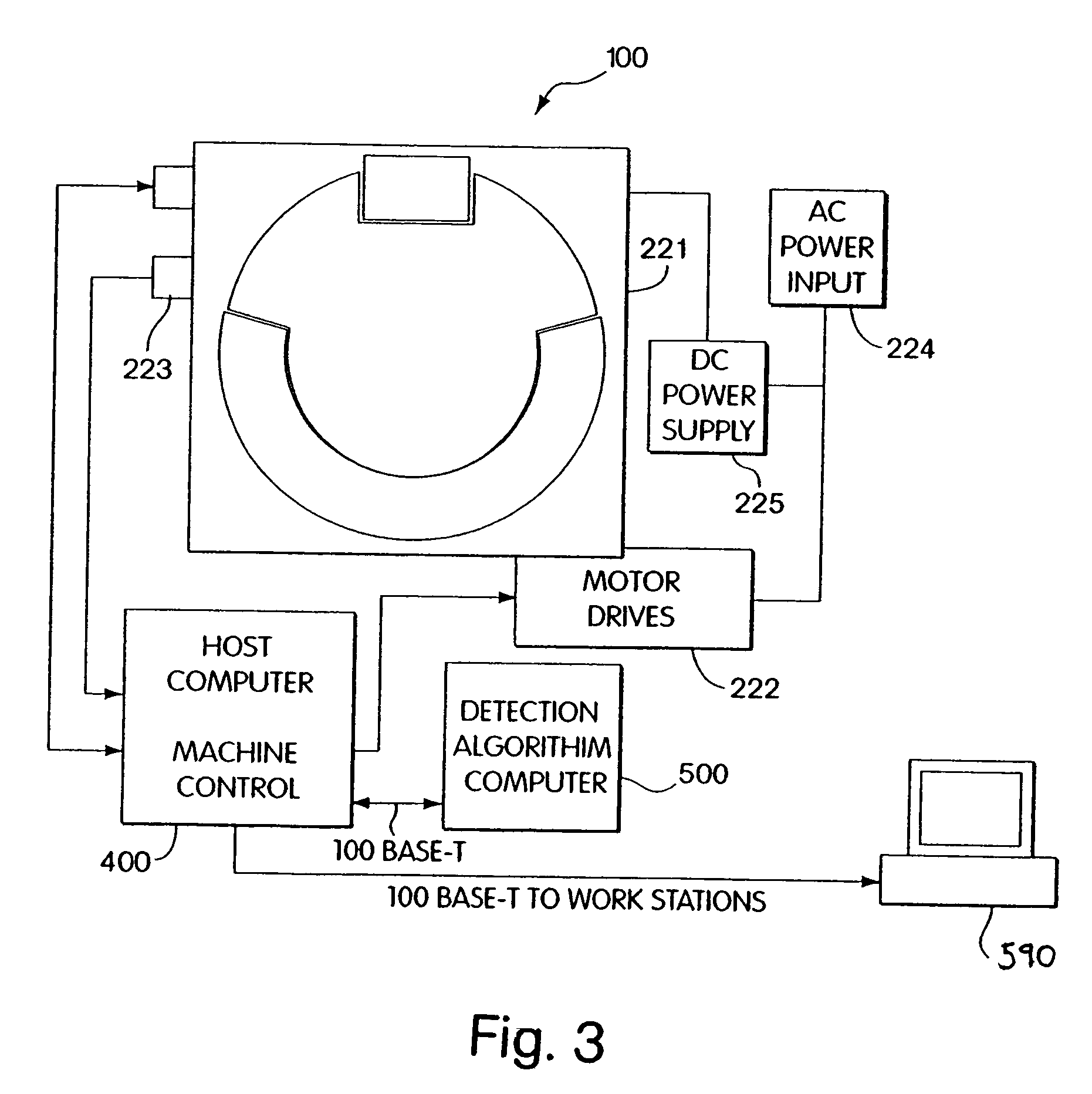
[0027]The present invention relates to a system and method for processing CT data to locate potential threats. The CT data may be obtained from a CT scanner of any known design. For example, the CT data may be obtained from a CT scanner of the prior art as shown in FIG. 1 and discussed above. Alternatively, the assignee of the present invention has devised a novel CT scanner having a reduced size, as set forth in the patent application entitled “Folded Array CT Baggage Scanner,” filed on even date herewith. FIG. 2 illustrates the positioning of a wide angle x-ray source 130 and detectors 131, 132, 133 on the ring 111 of a gantry 110 according to an embodiment of the folded array CT scanner. The ring 111 of the gantry 110 is substantially smaller than for conventional CT scanners with a similar size tunnel 120. The wide angle x-ray source 130 is located on the gantry 110 so that the x-ray beam intersects the entire area of the tunnel 120. Since the x-ray source 130 has a wider beam 1...


PUM

PropertyMeasurementUnit
angleaaaaaaaaaa
speedaaaaaaaaaa
CTaaaaaaaaaa

Abstract

The threat determination process for CT scan of baggage eliminates the need for complete reconstruction the bag. The CT scan data is analyzed during scanning to locate potential threats. The analysis is based upon a lineogram representing objects in the bag. The mass, size, location and atomic number of objects are determined based upon the lineogram data. Any potential threats are further subjected to data modification and reconstruction to enhance the view of the potential threat. Dual energy scanning may also be used to determine density for resolution of potential threats.

Description

RELATED APPLICATIONS[0001]This application claims priority to U.S. Provisional Application Ser. No. 60 / 442,246, filed Jan. 23, 2003.BACKGROUND OF THE INVENTION[0002]1. Field of the Invention[0003]The present invention relates to a Computed Tomography (CT) system for inspecting baggage for explosives or other contraband. More particularly, it relates to a Computed Tomography (CT) scanning process which does not require complete reconstruction.[0004]2. Discussion of Related Art[0005]Following the terrorist attacks on Sep. 11, 2001, the United States government decided to implement additional airport security. One of the security measures which were to be implemented was inspection of all checked baggage for explosives. In November 2001, Congress passed the Aviation and Transportation Security Act, which mandated 100% explosive detection screening of checked baggage by Dec. 31, 2002. It was expected that the screening requirements would be met through a combination of Explosive Detecti...

Claims


Application Information

Patent Timeline
Patent Type & Authority Patents(United States)
IPC IPC(8): G01N23/10G01N23/04G01V5/00
CPCG01V5/005
Inventor ELLENBOGEN, MICHAELBIIJANI, RICHARD ROBEHR
Owner REVEAL IMAGING TECH
Why Eureka
Try Eureka