External wall construction, sealing fixture, external wall panel, and external wall constructing method

a technology for external walls and constructing methods, applied in the direction of ceilings, construction materials, lighting support devices, etc., to achieve the effect of preventing water penetration into the construction, preventing rainwater penetration reliably, and easy engagemen

Inactive Publication Date: 2002-02-28
NICHIHA CORP
View PDF0 Cites 31 Cited by
  • Summary
  • Abstract
  • Description
  • Claims
  • Application Information

AI Technical Summary

Benefits of technology

0048] In this case, the front plate portion and the front resilient material can be easily engaged into the notched recess of the external wall panel. In addition, after constructing, the front resilient material is in a compressed state gradually expands, and extends sufficiently into a space of the notched recess of the external wall panel. In this way, the front resilient material presses and seals the joint clearance portion of the left and right external wall panels from the rear side, thereby it is possible to prevent rainwater penetration reliably.
0049] Therefore, according to the present external wall constructing method, there can be provided an external wall construction for preventing water penetration into the construction in a easily and reliably way.
0050] In addition, at the second step, the sealing fixture can be installed in a state that the rising plate portion is abutted against the side face which is close to the back surface in comparison with the notched recess at the external wall panel of the first column. Thus, the lateral alignment of the sealing fixture can be easily performed.

Problems solved by technology

In addition, there is a problem that, although the caulking material 929 is attached on the external wall construction 9, rainwater 6 or the like may penetrate into the construction.

Method used


Image

  • External wall construction, sealing fixture, external wall panel, and external wall constructing method
  • External wall construction, sealing fixture, external wall panel, and external wall constructing method
  • External wall construction, sealing fixture, external wall panel, and external wall constructing method

Examples


embodiment 1

[0100] An external wall construction according to embodiments of the present invention will be described with reference to FIG. 1 to FIG. 10.

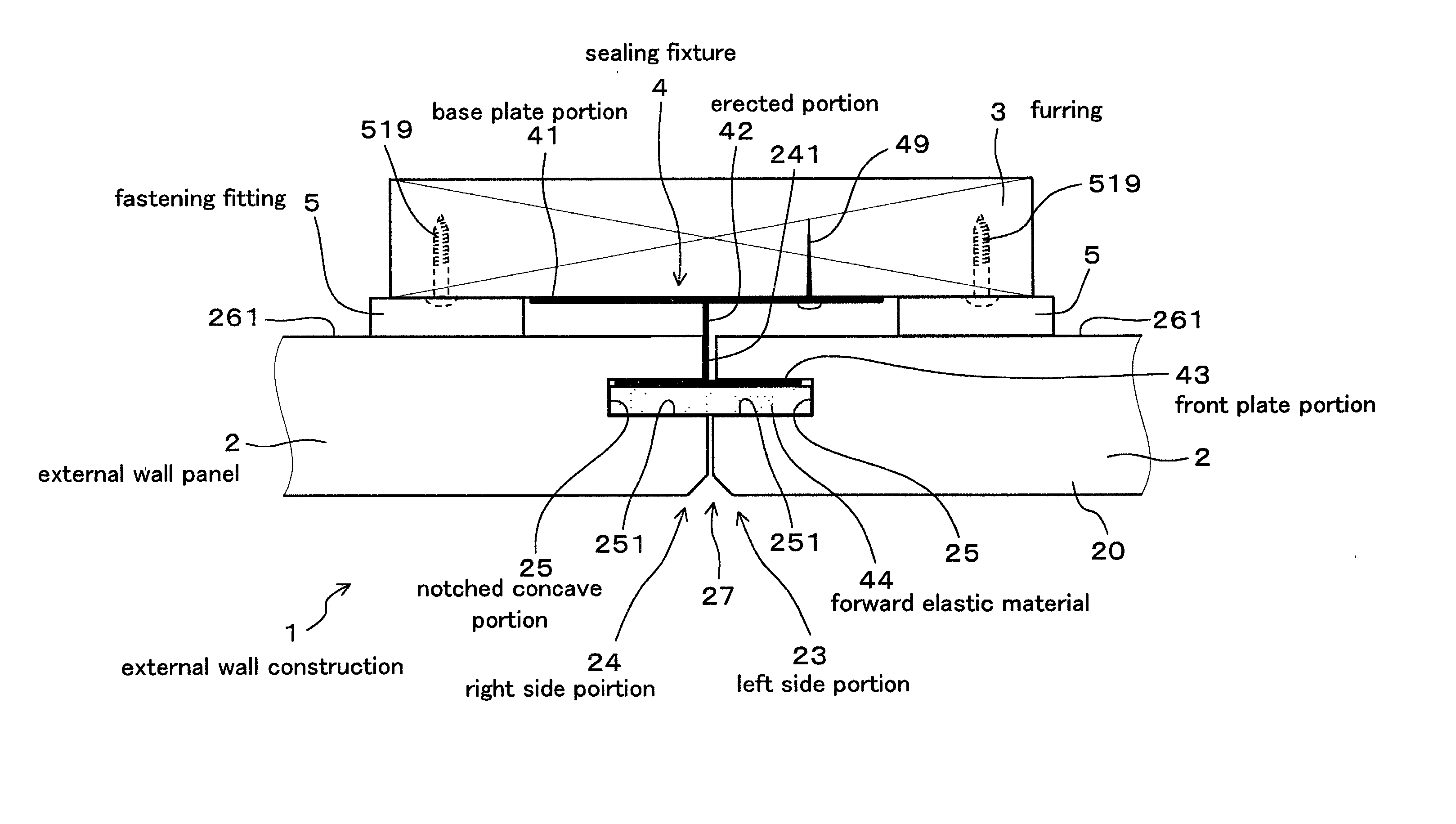
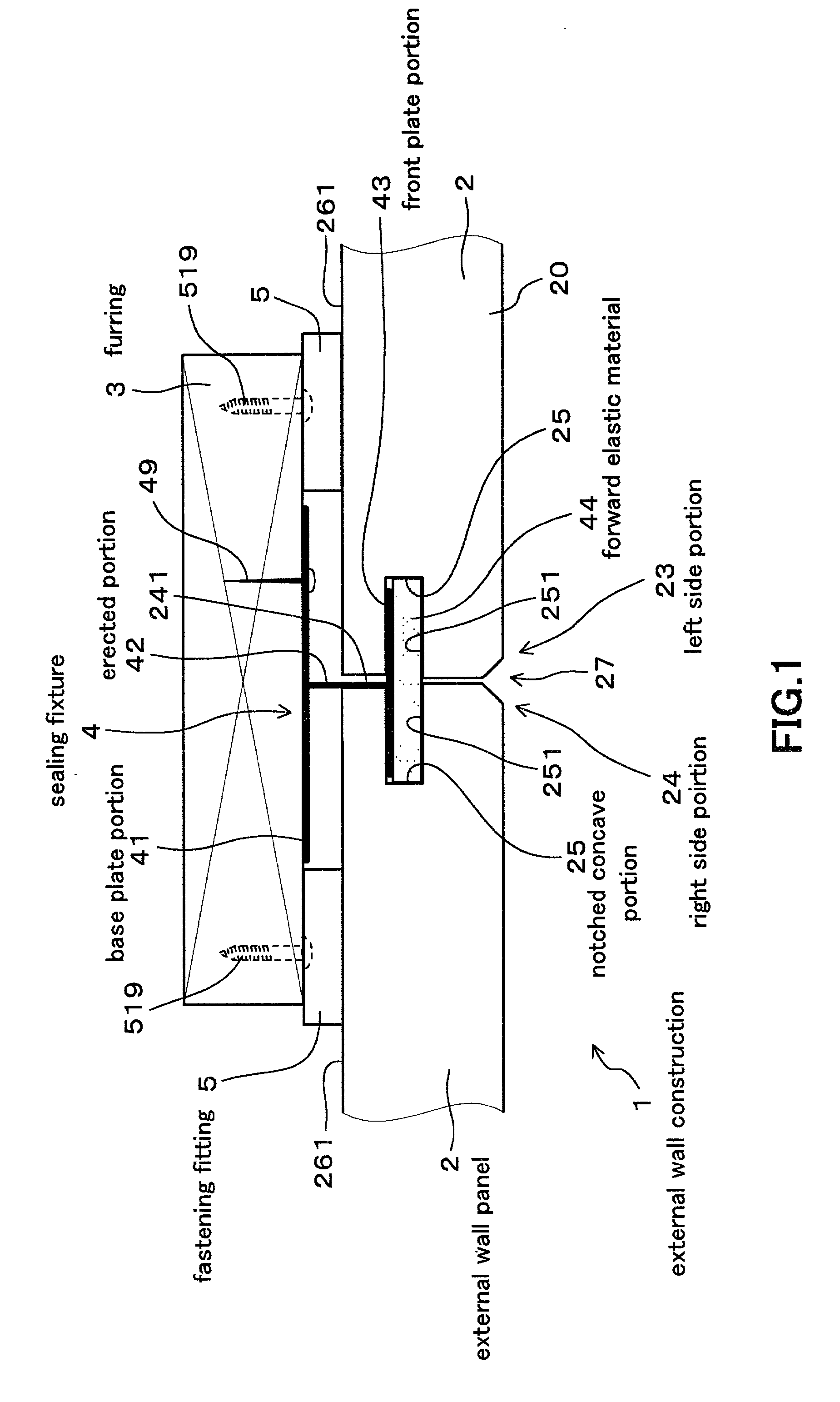
[0101] FIG. 1 is a lateral cross section illustrating an external wall construction 1 of the present embodiment, wherein a joint portion of the left and right external wall panels 2 is in the center.

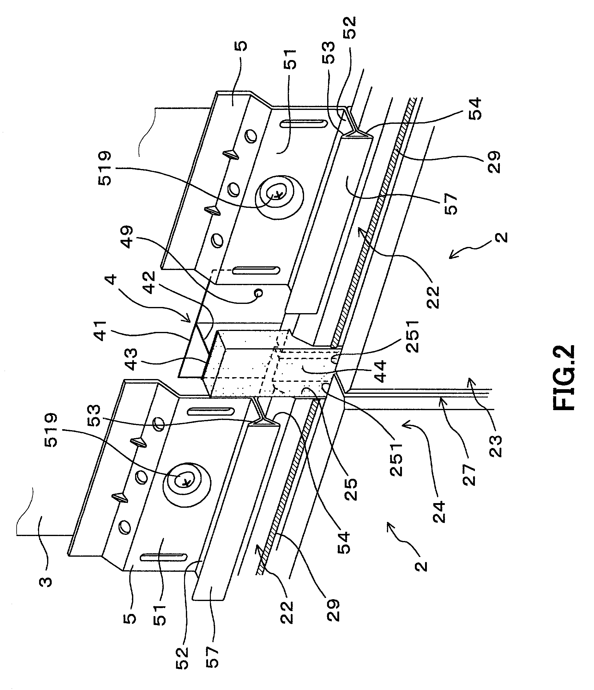
[0102] In the external wall construction 1 of the present embodiment, a securing metal fitting 5 is installed at the upper side portion and lower side portion of an external wall panel 2 (FIG. 3) , i.e., at an upper underlying tongue portion 22 and a lower overlying tongue portion 21, as shown in FIG. 1, FIG. 2 and FIG. 9, and the external wall panel 2 is mounted on the underlayment 3.

[0103] The external wall panel 2 has a notched recess 25 formed at a left side portion 23 and a right side portion 24 along the vertical direction, as shown in FIG. 3.

[0104] As shown in FIG. 1 and FIG. 2, the sealing fixture 4 (FIG. 4) is arranged between the adjacent ...

embodiment 2

[0138] As shown in FIG. 11 to FIG. 13, an external wall construction 12 having the rear resilient material 45 arranged on the front surface of the base plate portion 41 of the sealing fixture 4 is provided in this embodiment.

[0139] That is, in the sealing fixture 40, as shown in FIG. 12, the rear resilient material 45 is pasted at the front face of the left and right end portions 412 of the base plate portion 41 along the longitudinal direction.

[0140] The rear resilient material 45 is in closely contact with the back surface 26 of the external wall panel 2 as shown in FIG. 11 and FIG. 13.

[0141] The rear resilient material 45 is made of the same material as the front resilient material 44 shown in the embodiment 1.

[0142] In constructing the external wall construction 12, at the second step (refer to FIG. 10B) and the third step (refer to FIG. 10C) of the external wall constructing method shown in the embodiment 1, the rear resilient material 45 is brought into closely contact with th...

embodiment 3

[0149] The present embodiment describes an example of an external wall construction 13 in which a base plate portion 41 of a sealing fixture 4 is superimposed backwardly of a securing metal fitting 5, thereby fixing the sealing fixture 4 to an underlayment 3 together with the securing metal fitting 5.

[0150] The securing metal fitting 5 is fixed to the underlayment 3 by means of a screw 519 together with the sealing fixture 4.

[0151] The others are similar to embodiment 1.

[0152] In this case, a space for fixing the securing metal fitting 5 can be reduced. Therefore, as shown in FIG. 14, even in the case where a width of the underlayment 3 is small, the securing metal fitting 5 can be easily and reliably fixed.

[0153] For example, in the case where the underlayment 3 is a vertical furring strip having a small width, the securing metal fitting 5 can be easily and reliably fixed to the underlayment 3.

[0154] Otherwise, an advantageous effect similar to embodiment 1 is provided.


PUM


Abstract

An object of the present invention is to provide an external wall construction capable of inhibiting water penetration into the external wall construction reliably; and a sealing fixture, an external wall panel, and an external wall constructing method, which are used for the external wall construction. In the external wall construction, a securing metal fitting is installed at an upper side portion and a lower side portion of the external wall panel, and the external wall panel is mounted on an underlayment. The external wall panel has a notched recess formed on a left side portion and a right side portion along the vertical direction. A sealing fixture is arranged between the adjacent left and right external wall panels. The sealing fixture has a base plate portion fixed to the underlayment, a rising plate portion erected at the base plate portion, and a front plate portion arranged at the rising plate portion, wherein a front resilient material is provided at the front face of the front plate portion. The front resilient material and the front plate portion are engaged into a notched recess of the external wall panel.

Description

CROSS-REFERENCES TO RELATED APPLICATIONS[0001] The present application claims priority under 35 U.S.C. .sctn.119 to Japanese Patent Application No. 2000-241603, filed on Aug. 9, 2000, entitled "EXTERNAL WALL CONSTRUCTION, SEALING FIXTURE, EXTERNAL WALL PANEL, AND EXTERNAL WALL CONSTRUCTING METHOD". The contents of this application are incorporated herein by reference in their entirety.BACKGROUND OF THE INVENTION[0002] 1. Field of the Invention[0003] The present invention relates to an external wall construction for mounting an external wall panel on an underlayment using a securing metal fitting and further relates to a sealing fixture, an external wall panel, and an external wall constructing method used for the external wall construction.[0004] 2. Discussion of the Background[0005] Conventionally, there has been known an external wall construction: wherein a securing metal fitting is engagingly locked to an upper underlying tongue portion formed at an upper side portion of an exte...

Claims


Application Information

Patent Timeline
Patent Type & Authority Applications(United States)
IPC IPC(8): E04F13/08E04F13/26
CPCY10T403/7094E04F13/0864F16B2200/30
Inventor ITO, HIROSHI
Owner NICHIHA CORP
Why Eureka
Try Eureka