Led lighting equipment for vehicle
a technology for lighting equipment and vehicles, applied in the direction of lighting and heating equipment, fixed installations, instruments, etc., can solve the problems of increasing cost, power consumption, temperature when turned on, etc., and affecting the load of vehicles
- Summary
- Abstract
- Description
- Claims
- Application Information
AI Technical Summary
Problems solved by technology
Method used
Image
Examples
first embodiment
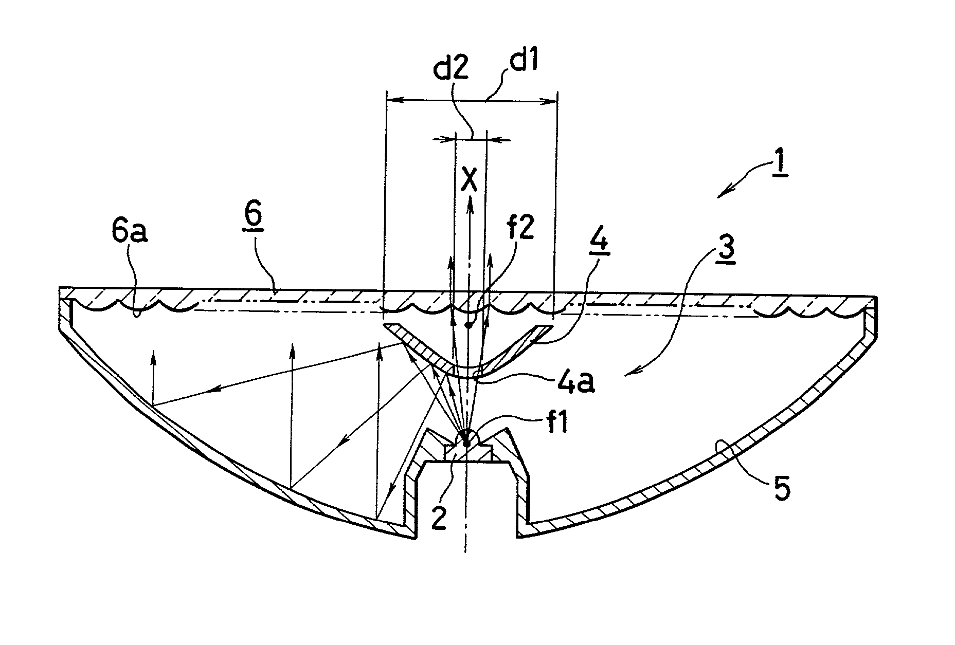
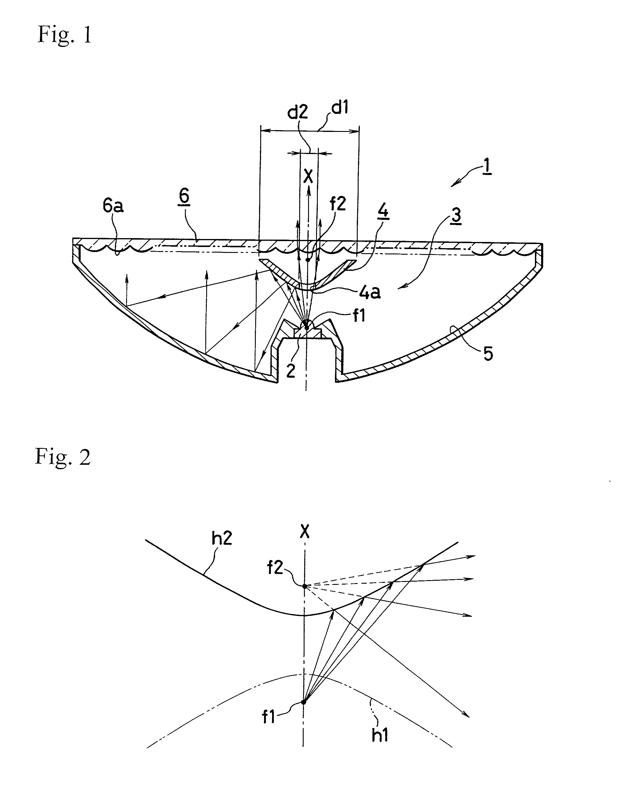
[0017] Now, the present invention will be described in detail, based on the embodiment shown in the drawing. In FIG. 1, the symbol 1 indicates a lighting equipment for vehicle according to the present invention, adopting an LED lamp 2 as in the prior art; however, in this invention, the LED lamp 2 is provide with a light emitting unit 3.
[0018] Said light emitting unit 3 comprises, as main components, a reflection surface of hyperboloid 4 having a transmission portion, and a reflection surface of paraboloid of revolution 5 4, and said LED lamp 2 is disposed at a predetermined position in respect to said reflection surface of hyperboloid 4.
[0019] Before describing the lighting equipment for vehicle 1 of the present invention, the properties of hyperbola will be explained briefly. As shown in FIG. 2, a pair of hyperbolae h1, h2 facing each other have respectively foci f1, f2. A hyperboloid of two sheets facing each other with both convex faces is obtained by the rotation of the hyperbo...
second embodiment
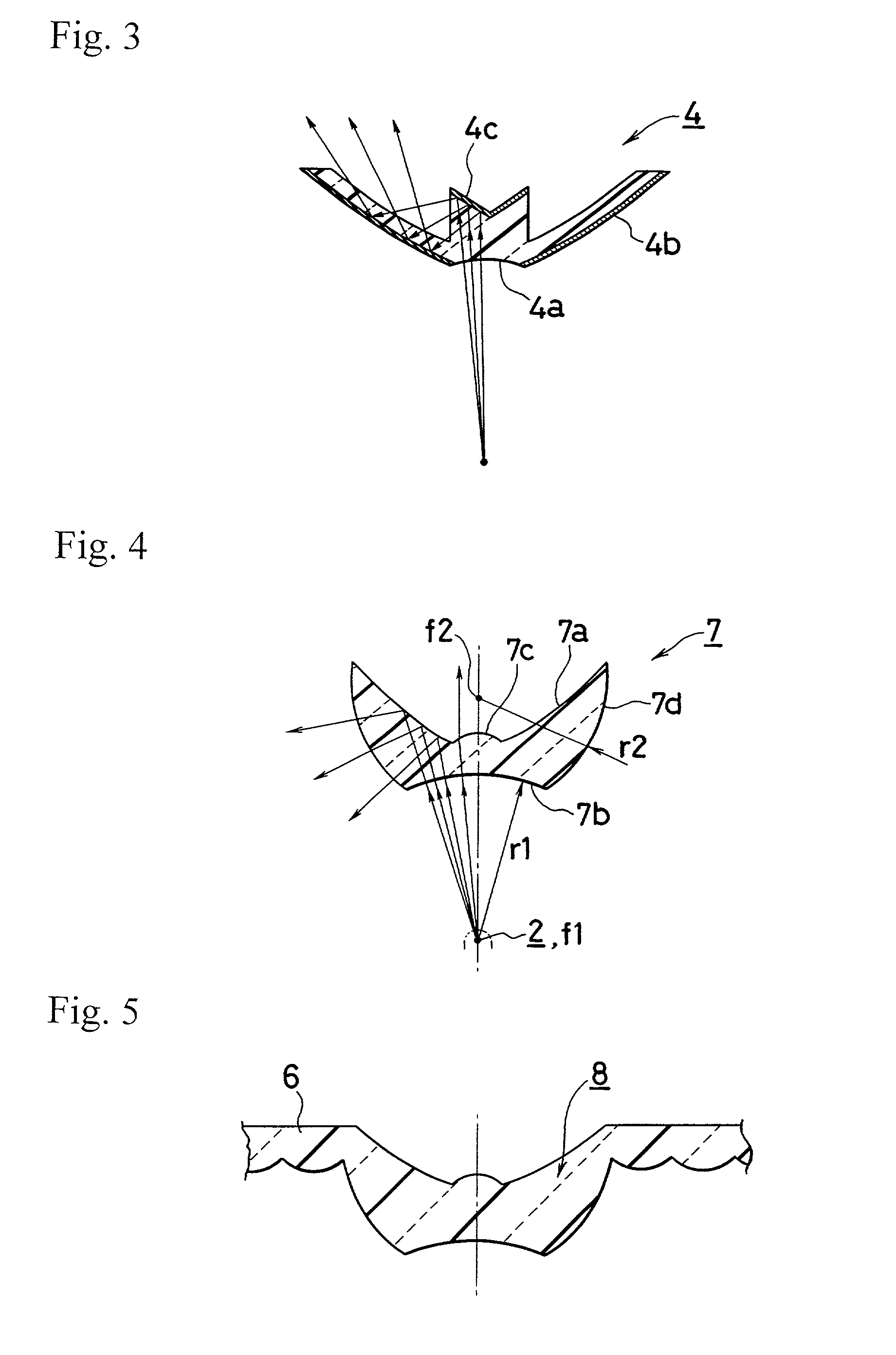
[0030] FIG. 3 shows the present invention, and this second embodiment concerns said reflection surface of hyperboloid 4. In the general characteristics of the LED lamp 2, light amount directed in the irradiation direction X is overwhelmingly important, and it is expected that the light amount passing through the transmission portion 4a is considerably high, though the aforementioned transmission portion 4a is small in diameter.
[0031] Consequently, it is preferable to diverge the light passing through said transmission portion 4a over an area as large as possible, for taking the balance of brightness with the other portions such as refection surface of paraboloid of revolution 5; therefore, in this second embodiment, a full reflection surface 4c made, for instance, in a substantially conical form, is provided on the optical path from said transmission portion 4a and light is reflected on the back of the reflection surface of hyperboloid 4 to enhance the divergence. Here, in this seco...
third embodiment
[0033] In opposition, the reflection surface of hyperboloid 7 of this third embodiment, the function of full reflection generating at the interface in a transparent resin at the critical angle produced by the difference of the transparent resin refractive index and the atmospheric refractive index is used and, in this embodiment, the hyperboloid 7a is formed at the interface with the atmosphere at the back of the transparent member viewed from the LED lamp 2.
[0034] The convenient range for the incident position of the light from the LED lamp 2 is made as an arc r1 surface around the first focus f1 or a plane, to form a transmission portion incidence portion 7b, and the back portion corresponding to said transmission portion incidence portion 7b is made as a convenient convex lens shape or others, to form a transmission portion exit portion 7c. Here, the diameter of the transmission portion exit portion 7c is decided similarly to the foregoing first embodiment.
[0035] A face 7d at the...
PUM
 Abstract
Description
Claims
Application Information
 - R&D
- Intellectual Property
- Life Sciences
- Materials
- Tech Scout
- Unparalleled Data Quality
- Higher Quality Content
- 60% Fewer Hallucinations
Browse by: Latest US Patents, China's latest patents, Technical Efficacy Thesaurus, Application Domain, Technology Topic, Popular Technical Reports.
© 2025 PatSnap. All rights reserved.Legal|Privacy policy|Modern Slavery Act Transparency Statement|Sitemap|About US| Contact US: help@patsnap.com


