Air conditioner outlet vent device

a technology for venting devices and air conditioners, which is applied in ventilation systems, lighting and heating apparatuses, heating types, etc., can solve the problem of difficult to set the gap between the second blades at a small level

Inactive Publication Date: 2002-02-28
MORIROKU
View PDF0 Cites 13 Cited by
  • Summary
  • Abstract
  • Description
  • Claims
  • Application Information

AI Technical Summary

Problems solved by technology

Although it is known that the smaller the gap between the blades, the better the air directing performance, in the above-mentioned conventional device, since it is necessary to prevent the pinion provided integrally with one of the second blades from interfering with the second blades present on opposite sides of the pinion, it is difficult to set the gaps between the second blades at a small level.

Method used


Image

  • Air conditioner outlet vent device
  • Air conditioner outlet vent device
  • Air conditioner outlet vent device

Examples


Embodiment Construction

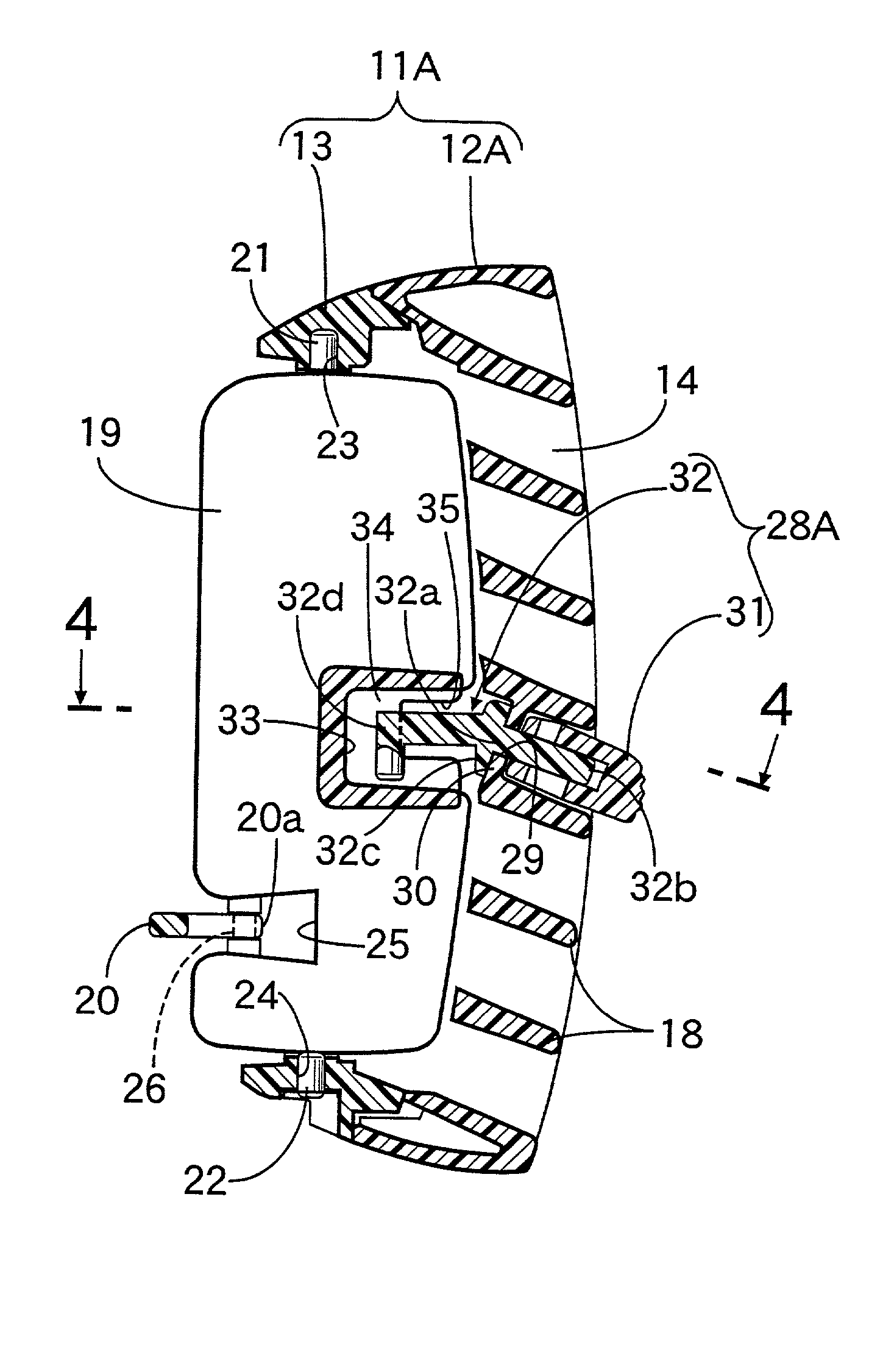
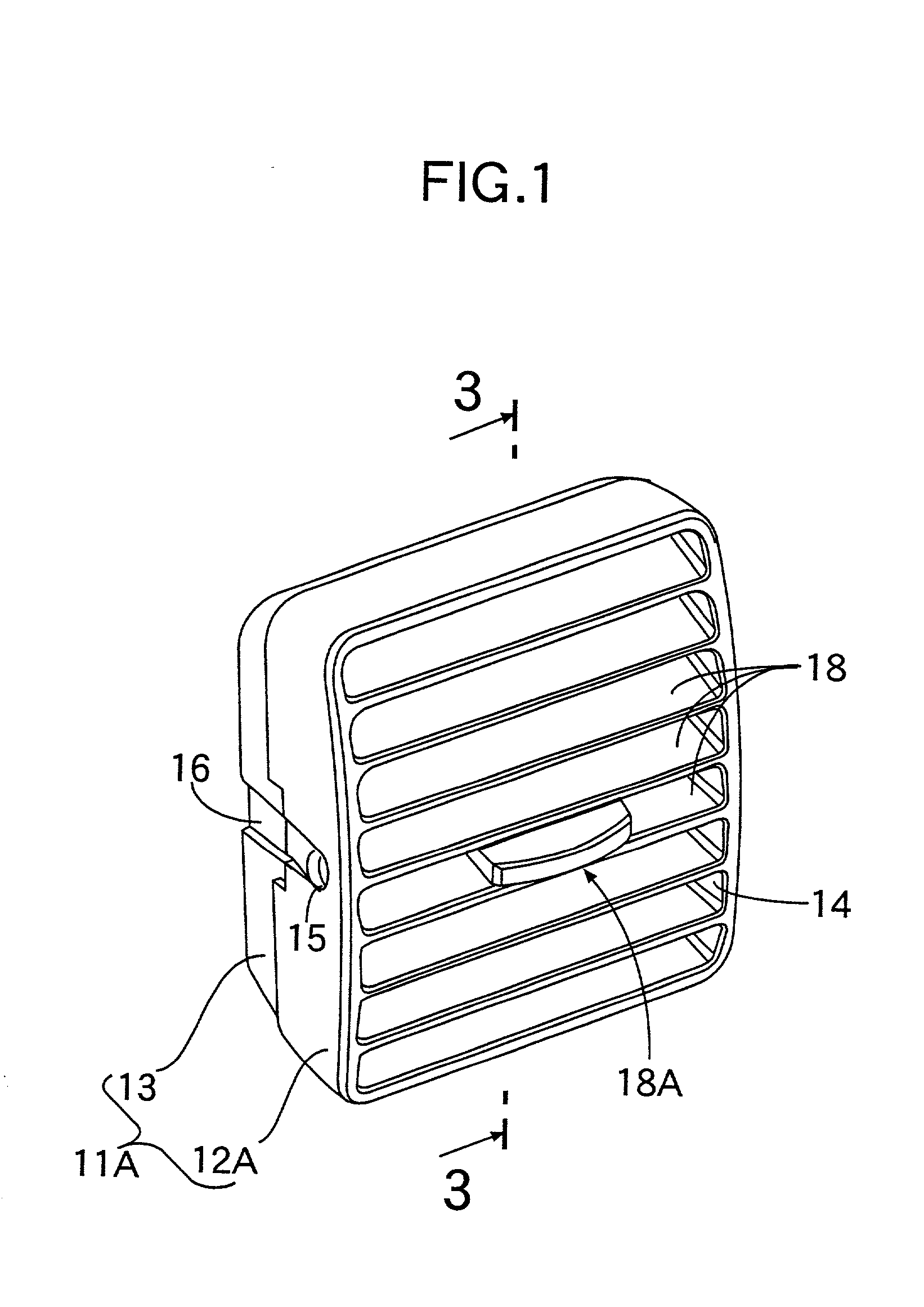
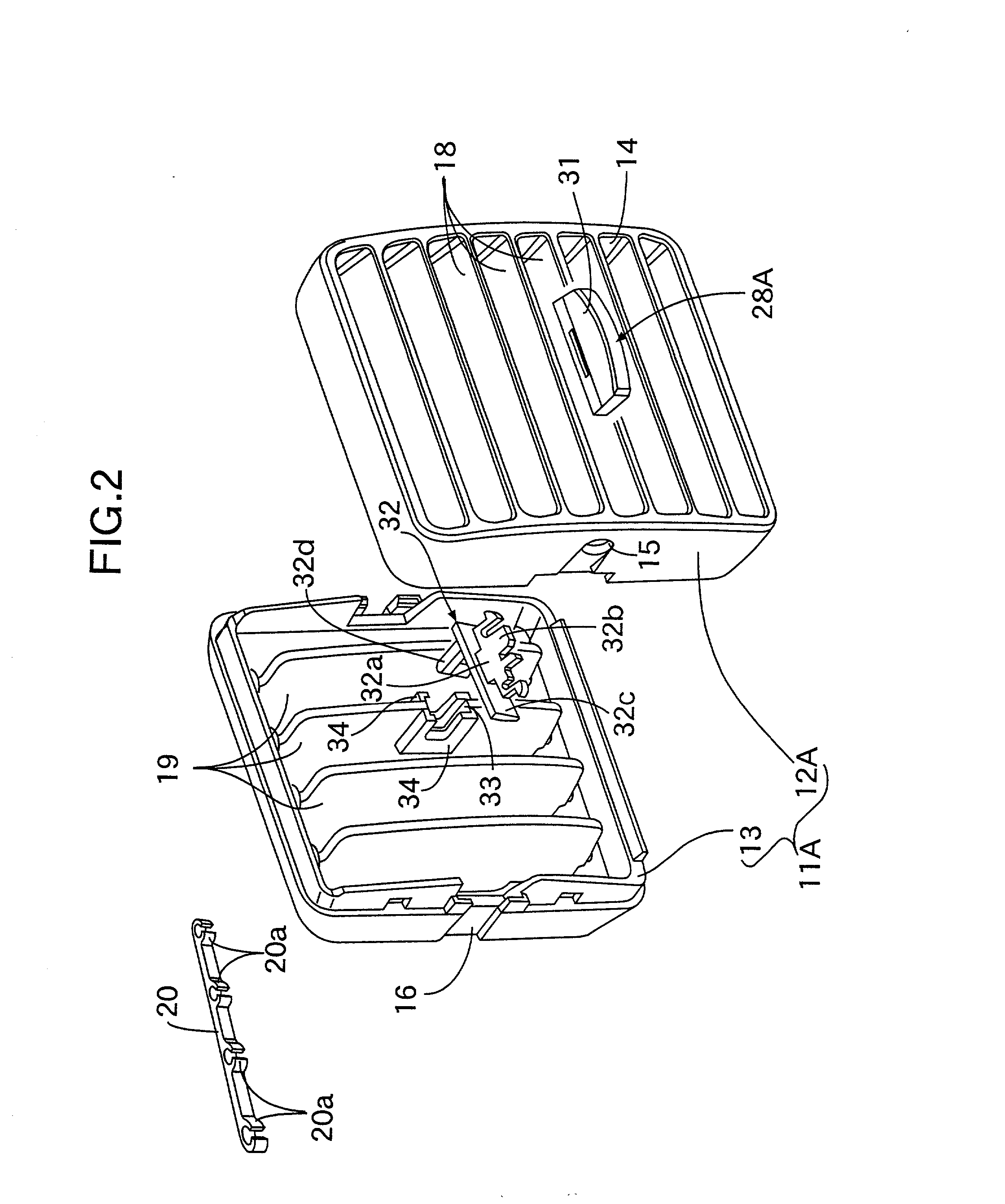
[0020] The first embodiment of the present invention is explained by reference to FIGS. 1 to 5. Firstly, in FIGS. 1 to 3, a housing 11A of the air conditioner outlet vent device is formed by joining a front housing 12A made of a synthetic resin in the form of a rectangular cylinder to a rear housing 13 made of a synthetic resin in the form of a rectangular cylinder, and has an outlet vent 14 having a rectangular cross section.

[0021] The housing 11A is mounted in, for example, an instrument panel of a passenger vehicle in a manner such that it can be pivoted in the vertical direction in such a manner that the open rear end of the housing 11A is connected to an air supply duct of an air conditioner.

[0022] Referring also to FIG. 4, support holes 15 are coaxially provided on opposite sides of the front housing 12A. Grooves 16 whose forward ends are connected to the support holes 15 are provided on the opposite sides of the front housing 12A and the rear housing 13 in such a manner that ...


PUM


Abstract

In an air conditioner outlet vent device in which a plurality of second blades are arranged behind a plurality of first blades in a direction perpendicular to the direction in which the first blades are arranged. The second blades are linked to a common link member, supported in a housing in a pivotable manner, and can be pivoted by an operating knob that can slide in the direction in which the second blades are arranged. A cut out recess opening toward the first blades and a pair of covers covering opposite sides of the cut out recess are provided on one of the second blades, and an engaging arm provided on the operating knob is inserted into the cut out recess so that the engaging arm can engage with one of the two covers. It is possible thereby to increase the amount of air blown out, and to enhance the air directing performance by making the gaps between the second blades relatively small.

Description

[0001] 1. FIELD OF THE INVENTION[0002] The present invention relates to an air conditioner outlet vent device that is suitable for use in an automobile, etc. and, in particular, to an improvement in an air conditioner outlet vent device comprising a plurality of first blades and a plurality of second blades that are arranged behind the first blades in a direction perpendicular to the direction in which the first blades are arranged, the second blades being connected to a common link member and supported in a housing in a pivotable manner so that the second blades can be pivoted by an operating knob that can slide in the direction in which the second blades are arranged.[0003] 2. DESCRIPTION OF THE RELATED ART[0004] Conventionally, such an air conditioner outlet vent device is already known as in, for example, Japanese Utility Model Registration Publication No. 6-41851, in which a rack formed on an operating knob slidably guided by a first blade is meshed with a fan-shaped pinion pro...

Claims


Application Information

Patent Timeline
Patent Type & Authority Applications(United States)
IPC IPC(8): B60H1/34F24F13/15
CPCB60H1/3428
Inventor YAMAGUCHI, TAKAYUKI
Owner MORIROKU
Why Eureka
Try Eureka