Biometric system and method for detecting duress transactions

a biometric system and duress detection technology, applied in the field of automatic teller machines, can solve the problems of harm to users, extortion, and inability to solve the security problem of atms, and achieve the effects of reducing the number of transactions, and improving the security of atms

Inactive Publication Date: 2002-04-04
ZINGHER JOSEPH P +1
View PDF0 Cites 108 Cited by
  • Summary
  • Abstract
  • Description
  • Claims
  • Application Information

AI Technical Summary

Problems solved by technology

While biometric identification is very useful in preventing fraudulent transactions, it does not solve the security problem posed by ATMs, specifically, extortion.
These methods, however, are not well suited to use in ATMs that use BID, as any act on the part of the user other than selecting a transaction and entering a transaction amount could alert the criminal that his crime has been reported, which in turn could result in harm to the user.
In addition, the system, having identified a duress transaction at an ATM, may; discretely notify the police while slowing down a transaction, giving police more time to respond; limit the funds available from a customer's account so that a criminal cannot get away with large sums of money; dispense marked bills to assist in positive identification of the criminal; or reject a transaction with an "unable to complete transaction" message and then slow down the transaction on any subsequent attempts.
Where the system is used for entry into or to enable the ignition system of an automobile, a BIDE could, in addition to sending a silent alarm to the police, cause the automobile to operate in an impaired manner to give police more time to respond to the emergency.

Method used


Image

  • Biometric system and method for detecting duress transactions
  • Biometric system and method for detecting duress transactions
  • Biometric system and method for detecting duress transactions

Examples


Embodiment Construction

[0033] While the invention is susceptible of embodiment in many different forms, there is shown in the drawings and will be described herein in detail, an exemplary embodiment and alternate exemplary embodiments of the invention. It should be understood, however, that the present disclosure is to be considered an exemplification of the principles of the invention and is not intended to limit the spirit and scope of the invention and / or claims of any embodiment illustrated.

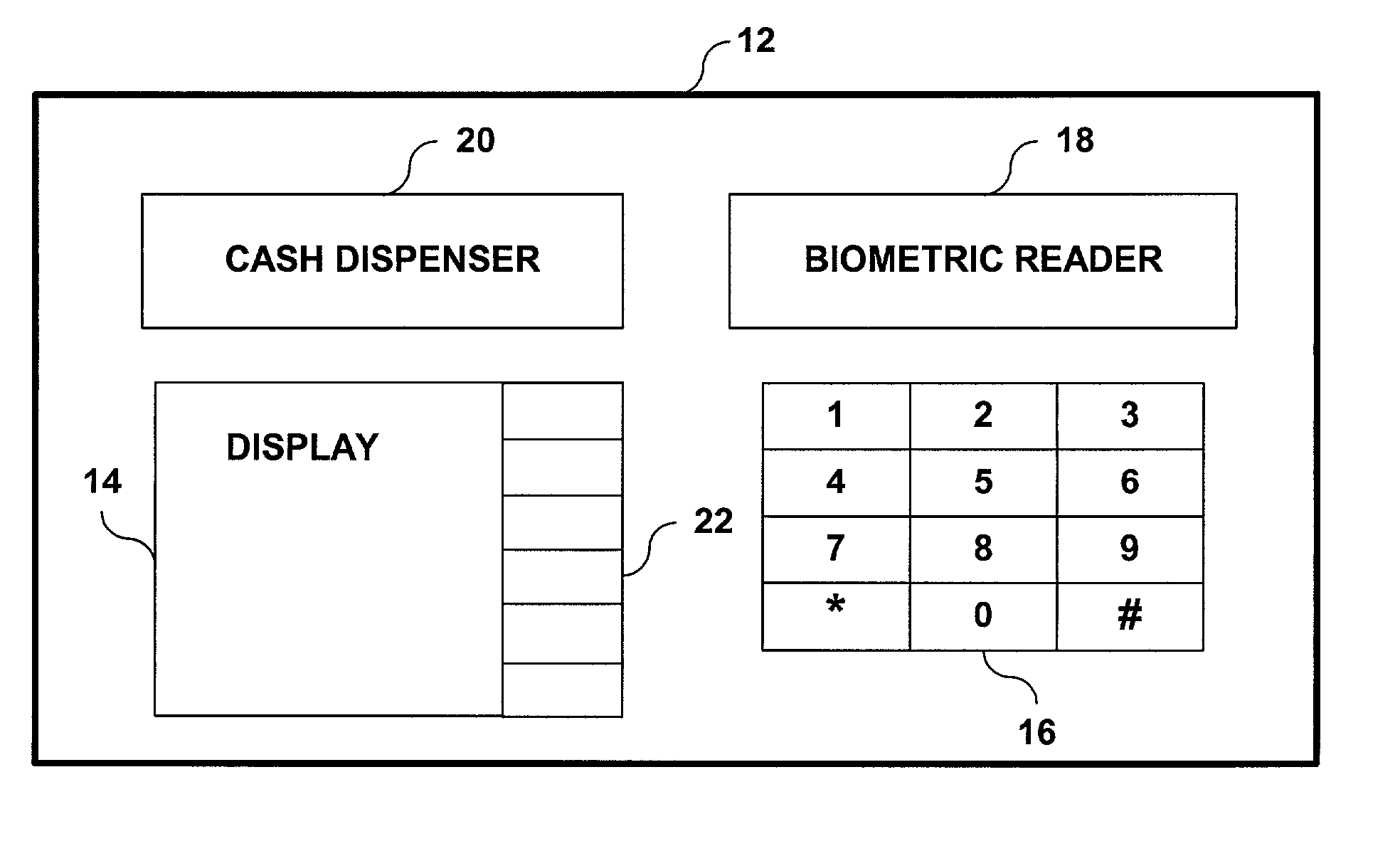
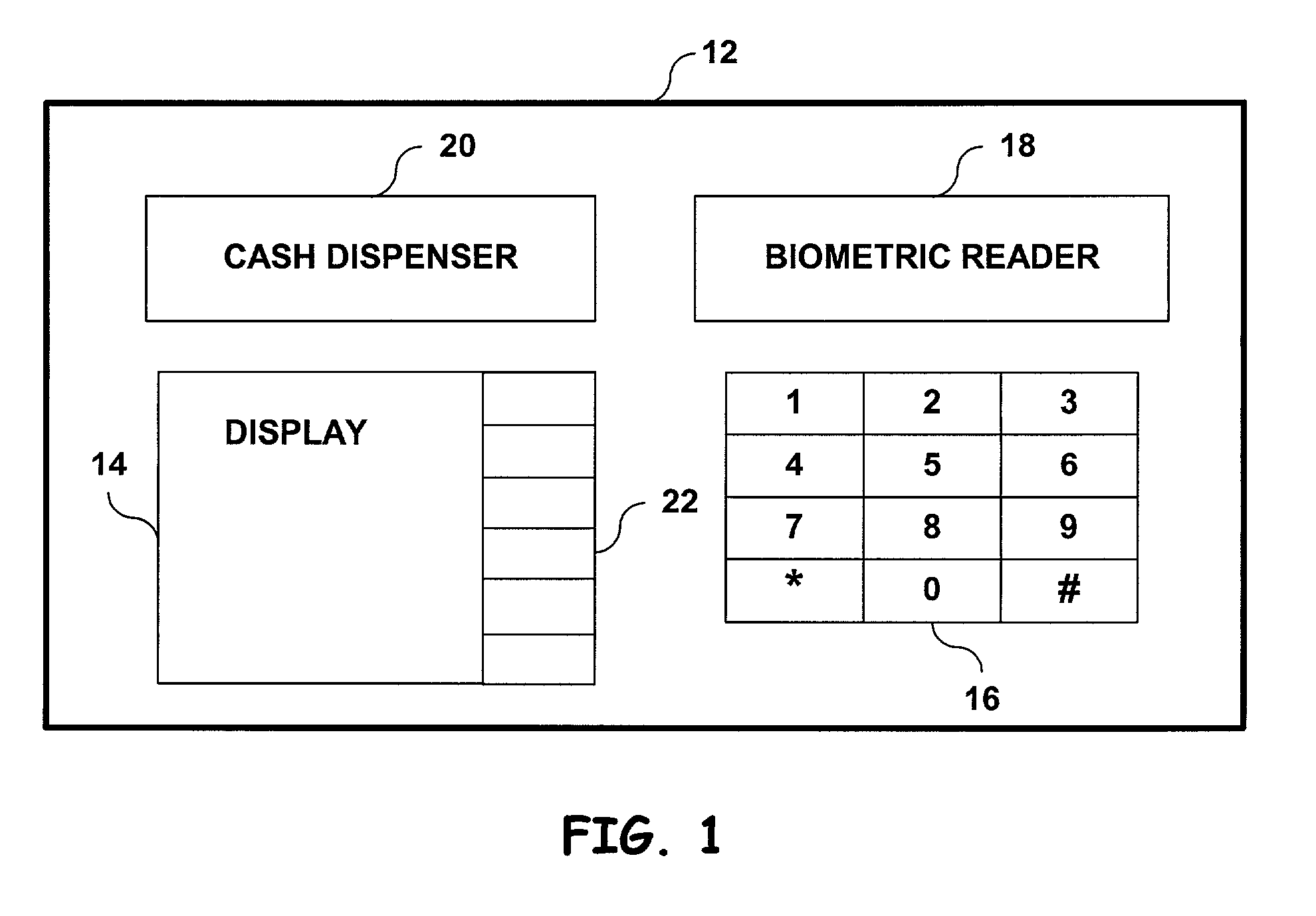
[0034] FIGS. 1 through 10 illustrate a system and method of the present invention, as well as alternate embodiments, for use with an ATM 12, such as that illustrated in FIG. 1, having a display 14, a keypad 16, a biometric reader 18, and a cash dispenser 20. The biometric reader 18 can include such components as, for example, lenses, lens covers and hoods, scanners, headrests (for retinal scanners), etc., in addition to routines stored in a memory to execute biometric identifications. Function buttons 22 are illust...


PUM


Abstract

A system for responding to a duress identification made at a biometric identification site. The system may include a processor, a memory, a biometric reader for collecting biometric information about a user, wherein the biometric information is used for determining if the user is an authorized user of the system. The system may also include a set of instructions stored in the memory, the set of instructions executable by the processor to determine whether the biometric information represents a normal identification or a duress identification; if the biometric information represents a duress identification, the system may initiate an emergency response, such as (for example) triggering a silent alarm.

Description

[0001] The inventors claim priority to U.S. Provisional Patent Application No. 60 / 237,584, entitled "Biometric System And Method For Detecting Duress Transactions at Automated Teller Machines," filed on Oct. 3, 2000, the entirety of which is expressly incorporated by reference.[0002] 1. Field of the Invention[0003] The present invention relates to automated teller machines (ATMs) and more particularly to a method and system for detecting transactions made under duress at ATMs using biometric measurements.[0004] 2. Description of Related Art[0005] With the advent of the automatic teller machine (ATM), it has become possible for banking withdrawals to be made without the assistance of human bank personnel or agents. For example, a customer may use an ATM to make deposits or withdrawals from a checking or savings account, or to determine the balance of such an account. Point-of-sale systems, where users may have purchases of, e.g., gasoline, groceries, or airline tickets, etc., directl...

Claims


Application Information

Patent Timeline
Patent Type & Authority Applications(United States)
IPC IPC(8): G06K9/00G07C9/00G07F7/10G07F19/00G07G3/00G08B25/01
CPCG06K9/00597G06Q20/341G06Q20/382G07C9/00158G08B25/016G07F7/1083G07F19/20G07F19/207G07G3/003G07F7/1008G07C9/37G06V40/18
Inventor ZINGHER, JOSEPH P.ZINGHER, ABRAHAM R.
Owner ZINGHER JOSEPH P
Why Eureka
Try Eureka