Case for Archery Equipment

a technology for archery equipment and cases, applied in the field of cases for archery equipment, can solve the problems of large equipment, large equipment, and relatively delicate equipment, and achieve the effect of non-deformation

Inactive Publication Date: 2002-04-11
PLANO MOLDING CO LLC
View PDF0 Cites 6 Cited by
  • Summary
  • Abstract
  • Description
  • Claims
  • Application Information

AI Technical Summary

Benefits of technology

0008] It is therefore a general object of the present invention to provide a protective case for the transportation

Problems solved by technology

Transporting archery equipment, such as bows and arrows, has always been a difficult undertaking.
By their very nature, the equipment is large and cumbersome.
The equipment is also relatively delicate in comparison to its size.
In particular, modern bows have very complex structure in order to provide the sophisticated functions now expected.
While a bow may be disassembled for transportation, it is considered a major disadvantage if this is necessary.
Accuracy is lost if these bows are disassembled.
However, the bows and arrows are also very delicate when subjected to forces different from those of ordinary operation.
Slight or unseen damage to bows can result in catastrophic failure of the equipment, which could even injure the user.
The slightest tweak, curve or bend in the arrow shaft will cause the arrow to fly off course when in use, or with carbon fiber, an off-axis impact can destroy the arrow shaft.
For many reasons, there are obvious disadvantages to the soft-sided cases.
First, and foremost, is the lack of protection afforded the equipment inside.
As a result, they have rather limited usefulness for serious archers, or those concerned about the condition of their equipment.
Without a stiff exterior panel, the level of protection afforded is only sufficient for the infrequent or occasional user.
One disadvantage is the size of such a case.
Available only in conventional rectangularly-shaped designs, there

Method used


Image

  • Case for Archery Equipment
  • Case for Archery Equipment
  • Case for Archery Equipment

Examples


Embodiment Construction

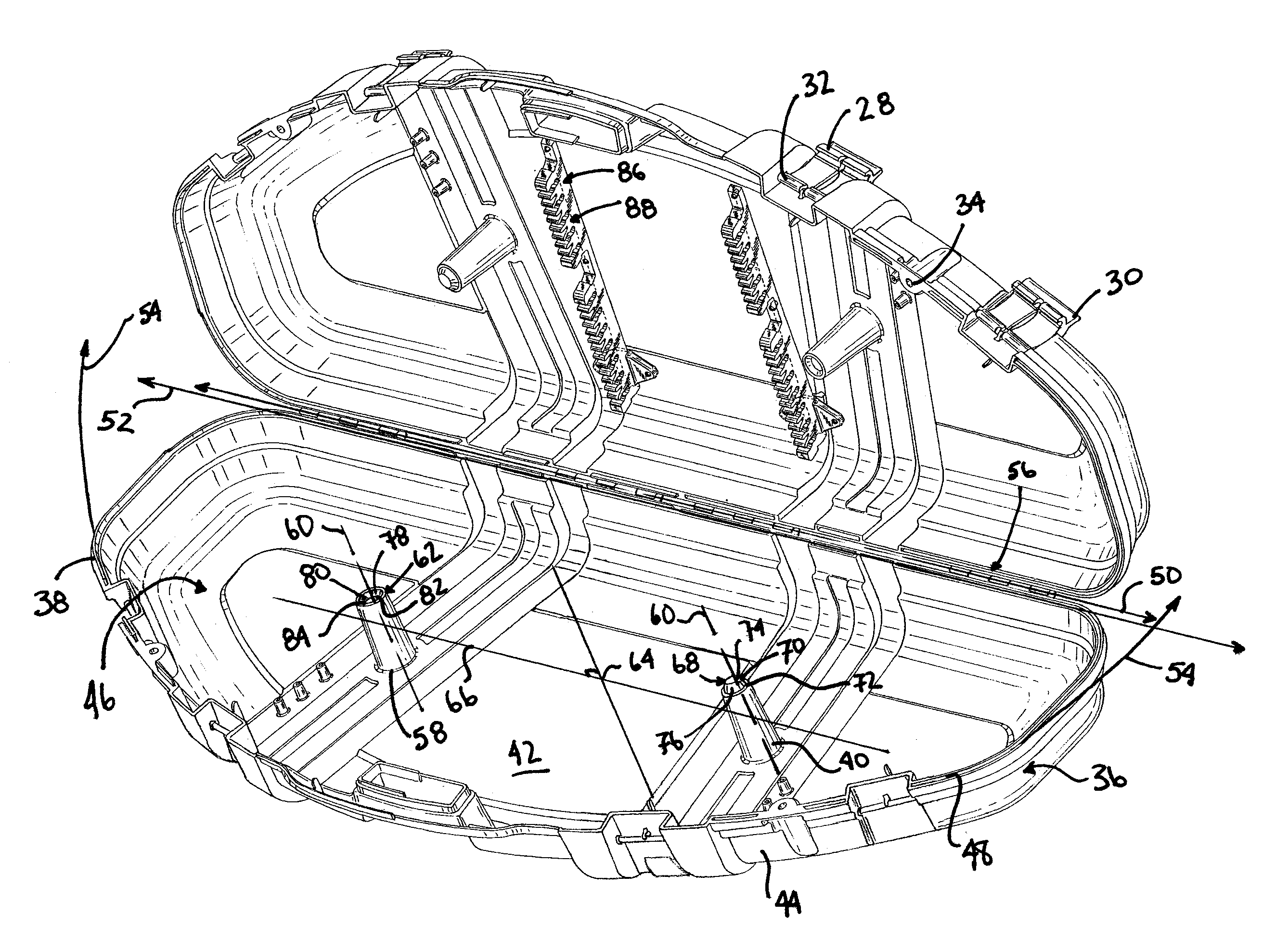
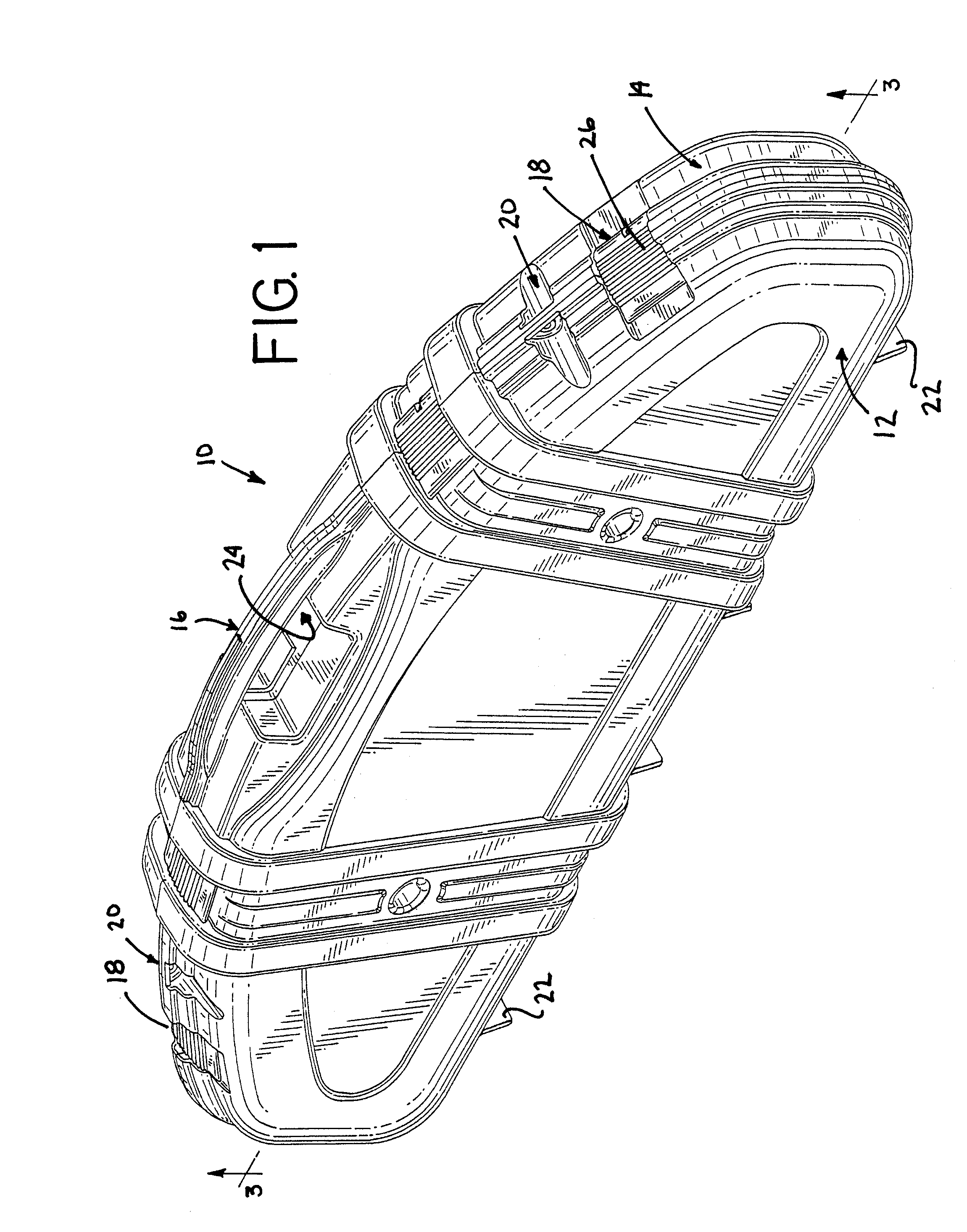
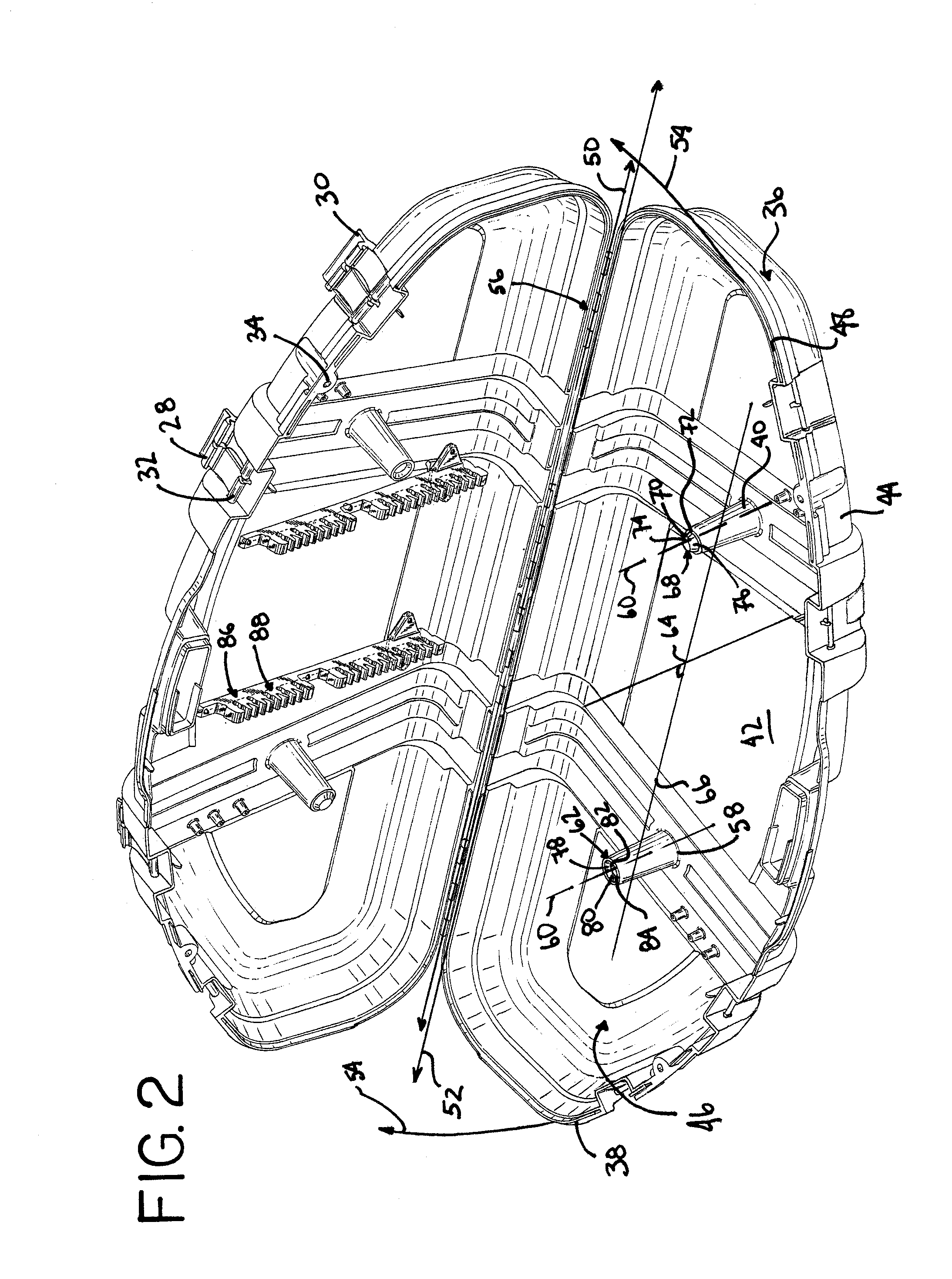
[0026] The present invention relates to a protective case for transporting and / or storing archery implements, preferably at least a bow and a plurality of arrows. Generally, the case 10 of the present invention shown in FIGS. 1-5, includes interengaging halves, a first half portion 12 and a second half portion 14 which are interconnected along a hinge line for movement between an open position, FIG. 2, and a closed position, FIGS. 1 and 3. As shown in FIG. 1, the case 10 also includes a handle 16, a plurality of latching devices 18, locking members 20, and a plurality of feet 22.

[0027] The handle 16 is formed by cooperation of the first half portion 12 and the second half portion 14. A passage 24 provided below the handle 16 for receiving the hand or fingers of an operator enables one to carry or move the case 10. Each latching device 18 in FIG. 2 includes an arm 26 and a catch 28. The arm 26 is movably secured to the case 10, and preferably to the second half portion 14. The prefer...


PUM


Abstract

<heading lvl="0">Abstract of Disclosure</heading> A case for archery equipment includes, interengaging first and second half portions connected for movement between open and closed positions. The first half portion includes a first wall defining a first interior recess and having a first mating rim. The first half portion further includes a plurality of first supports formed in the first wall, and located within the first interior recess. The second half portion includes a second wall defining a second interior recess and having a second mating rim. The second half portion further includes a plurality of second supports formed in the second wall and located within the second interior recess. Each first support has a first longitudinal axis and is aligned along a common first axis which intersects each first longitudinal axis normally within and defining a first common plane. Each second support has a second longitudinal axis and is aligned along a common second axis which intersects each second longitudinal axis normally within defining a second and common plane. The first and second planes are parallel and offset in the open position and aligned in opposition in the closed position such that each first support engages each said second support in mating contact. A load applied to the case in a closed position is distributed among the first and second supports and the first and second mating rims, resulting in a protective zone defined by the first and second interior recesses.

Description

Background of Invention[0001] The present invention relates generally to a case for archery equipment, and more particularly, to a molded, protective case which is adapted for easy, low-cost mass production manufacture and which prevents damage to the equipment stored therein, by even distribution of loads and forces thereupon.[0002] Transporting archery equipment, such as bows and arrows, has always been a difficult undertaking. By their very nature, the equipment is large and cumbersome. The equipment is also relatively delicate in comparison to its size. In particular, modern bows have very complex structure in order to provide the sophisticated functions now expected. While a bow may be disassembled for transportation, it is considered a major disadvantage if this is necessary. Accuracy is lost if these bows are disassembled. However, the bows and arrows are also very delicate when subjected to forces different from those of ordinary operation. Slight or unseen damage to bows ca...

Claims


Application Information

Patent Timeline
IPC IPC(8): A63B71/00F41B5/14
CPCF41B5/1457A63B71/0036
Inventor FIORE , JOSEPH F. II
Owner PLANO MOLDING CO LLC
Why Eureka
Try Eureka