Eureka AIR delivers breakthrough ideas for toughest innovation challenges, trusted by R&D personnel around the world.

High efficiency pneumatically driven electric power generator

Inactive Publication Date: 2002-04-25
WESTINGHOUSE AIR BRAKE CO
View PDF1 Cites 1 Cited by
  • Summary
  • Abstract
  • Description
  • Claims
  • Application Information

AI Technical Summary

Benefits of technology

[0005] It is, therefore, one of the primary objects of the present invention to provide a simple and inexpensive generator for supplying electrical power for a railway vehicle.
[0006] Another object of the present invention is to provide a small and lightweight generator for supplying electrical power for a railway vehicle.
[0007] Still another object of the present invention is to provide an electric power generator for a railway vehicle which does not require gears and clutches to extract rotary mechanical power from an axle of the railway vehicle.
[0009] A further object of the present invention is to provide a small electric power generator employing a brake airline as an air supply and using so little air that even when such a generator is on all the railway vehicles in a long freight train, the air used does not seriously add to the airline leakage rate.

Problems solved by technology

These generators are usually much larger, complex and expensive and are heavier than is necessary for generating a small amount of electrical power.

Method used


Image

  • High efficiency pneumatically driven electric power generator
  • High efficiency pneumatically driven electric power generator
  • High efficiency pneumatically driven electric power generator

Examples


Embodiment Construction

[0023] Prior to proceeding to the much more detailed description of the present invention, it should be noted that identical components having identical functions have been identified with identical reference numerals throughout the several views illustrated in the drawing figures, for the sake of clarity and understanding of the invention.

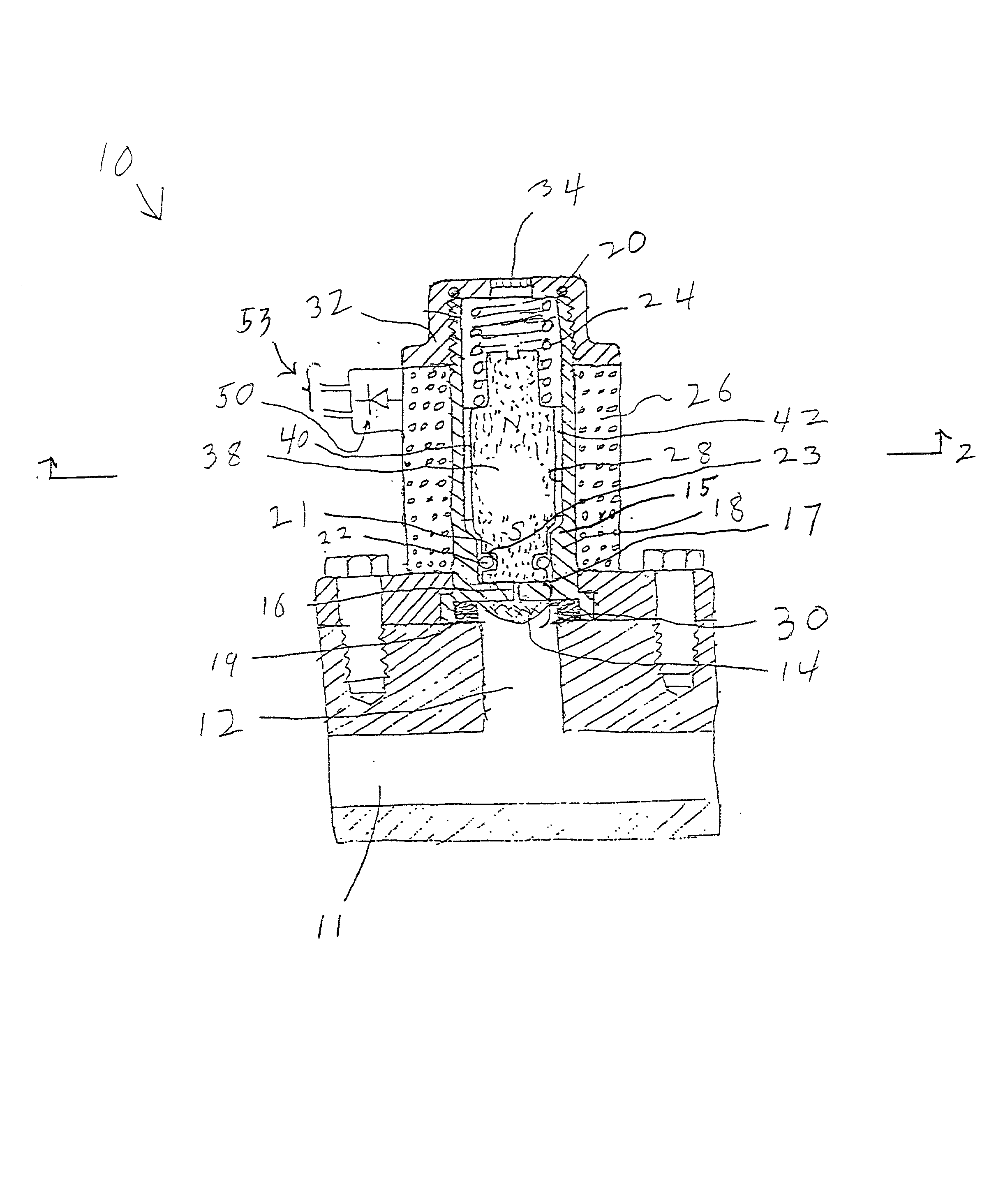
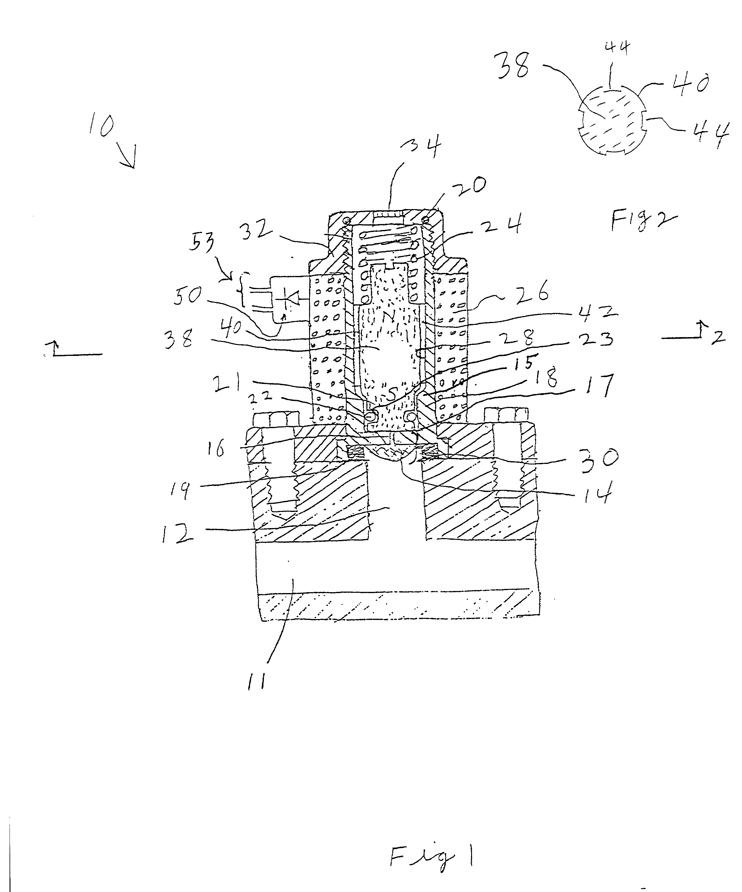
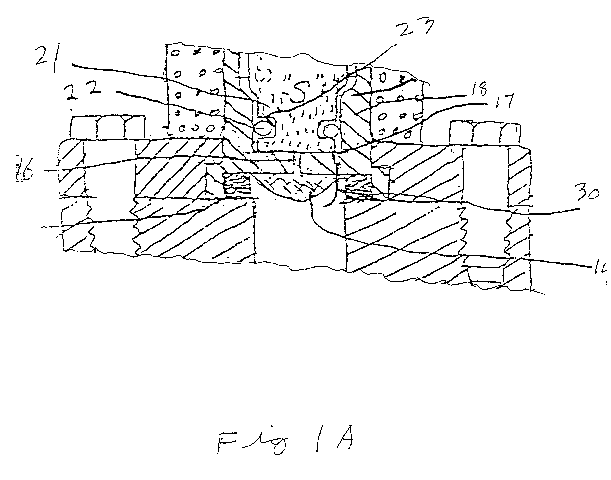
[0024] Attention is directed to FIG. 1 which is a schematic median section of the invention. The pneumatically driven electric power generator, generally designated 10, has a piston 21 and a cylinder 18. Piston 21 is free to move in and out of cylinder 18. FIG. 1 shows piston 21 disposed in cylinder 18 and FIG. 3 shows piston 21 outside of cylinder 18. During operation, piston 21 moves cyclically between the position shown in FIG. 1 and the position shown in FIG. 3. A seal, preferably O-ring 22, is provided to prevent airflow between piston 21 and cylinder 18 when piston 21 is disposed within cylinder 18. In the presently preferred embodiment, O-r...


PUM


Abstract

This invention is a pneumatically driven electric power generator. It includes a cylinder having one end connected to an air supply passage for receiving pressurized air and it has another end open. The invention has a piston having an associated magnetic moment. A portion of the piston is free to move into and out of the open end of the cylinder. Sealing means are provided to prevent airflow between the piston and the cylinder when a portion of the piston is located within the cylinder. Piston return means are provided which tend to force the piston from a position outside of the cylinder to a position having a portion of the piston inside the cylinder, so that the piston oscillates, moving into and out of the cylinder, driven by air supplied through the air supply passage. One or more electric coils are placed to enclose changing magnetic flux caused by the magnetic moment associated with the oscillating piston whereby an emf is generated in the coil(s) so that an external circuit connected to the coil(s) to complete a circuit through the coil(s) may receive electric power from the coil(s).

Description

[0001] The present invention relates, in general, to pneumatically driven electric power generators and, more particularly, the instant invention relates to electric power generators for railway vehicles.[0002] The classical railroad airbrake system which was derived from the Westinghouse airbrake has, in recent years, been augmented by introducing electrical controls, while maintaining the reliability inherent in the fundamental pneumatic portions of the classical airbrake system. These electrical control systems generally require batteries in the individual railway vehicles and it is desirable to provide a generator on each car to maintain the batteries in a charged condition. For some proposed electrically controlled pneumatic systems, a power level as small as one Watt may be sufficient. Prior art generators for railway vehicles generally employ rotary mechanical power obtained from an axle of the railway vehicle. A generator may be positioned near an axle and receive power thro...

Claims


Application Information

Patent Timeline
IPC IPC(8): H02K7/18H02K35/02
CPCH02K35/02H02K7/1892
Inventor CARROLL, JOHN B.
Owner WESTINGHOUSE AIR BRAKE CO
Why Eureka
Eureka Blog
Learn More