

Capacity scaling and functional element redistribution within an in-building coax cable internet Access system
- Summary
- Abstract
- Description
- Claims
- Application Information
AI Technical Summary
Benefits of technology
Problems solved by technology
Method used
Image

Examples
Embodiment Construction
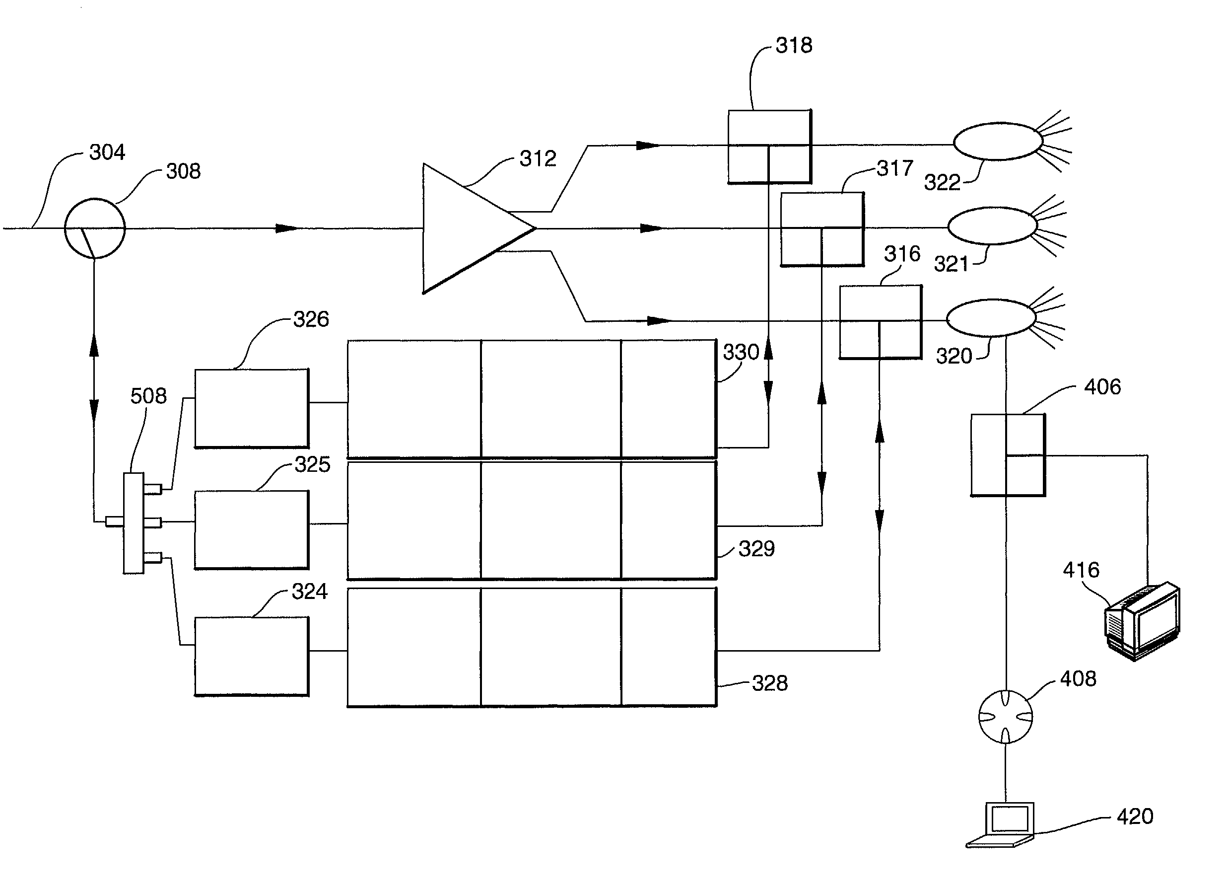
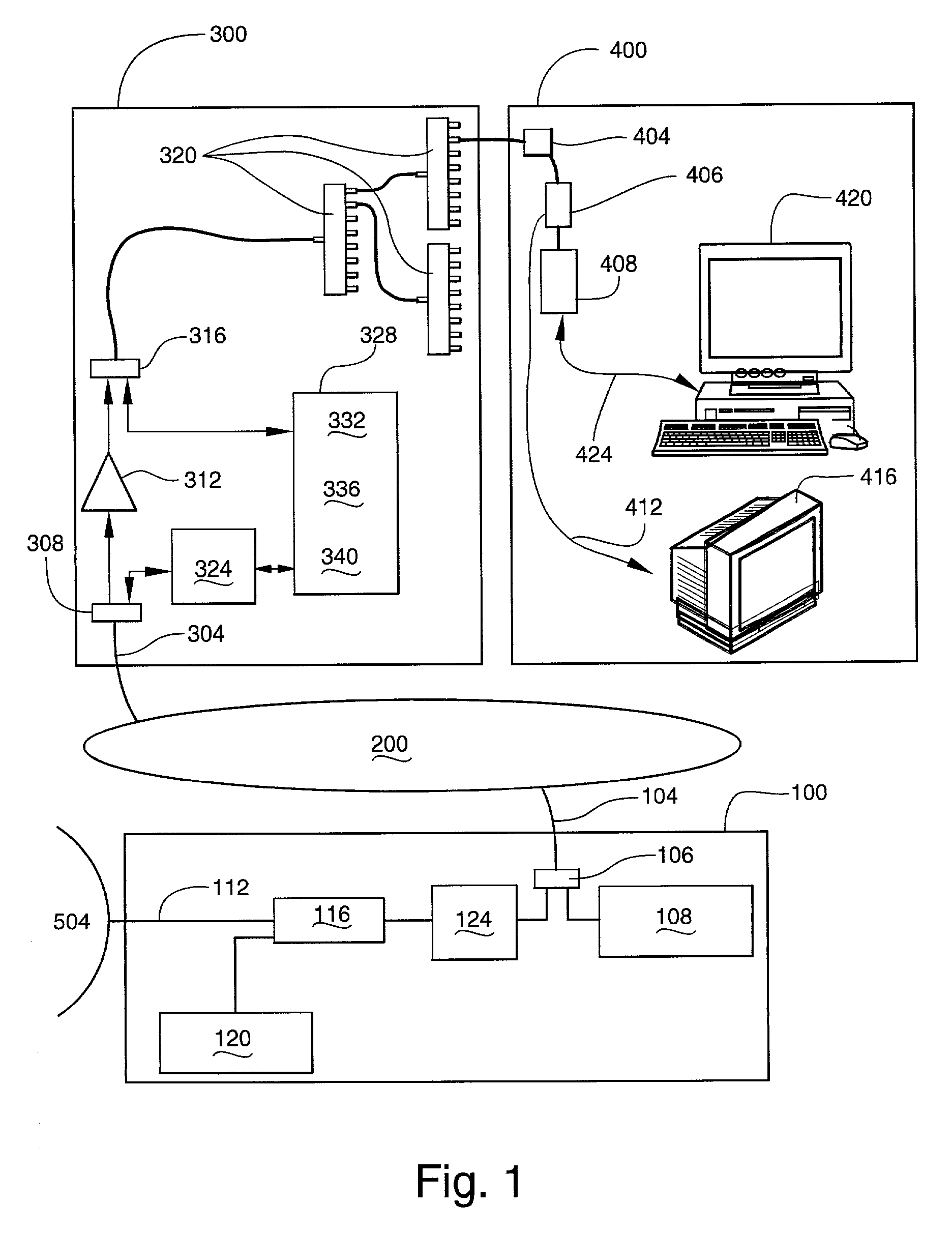
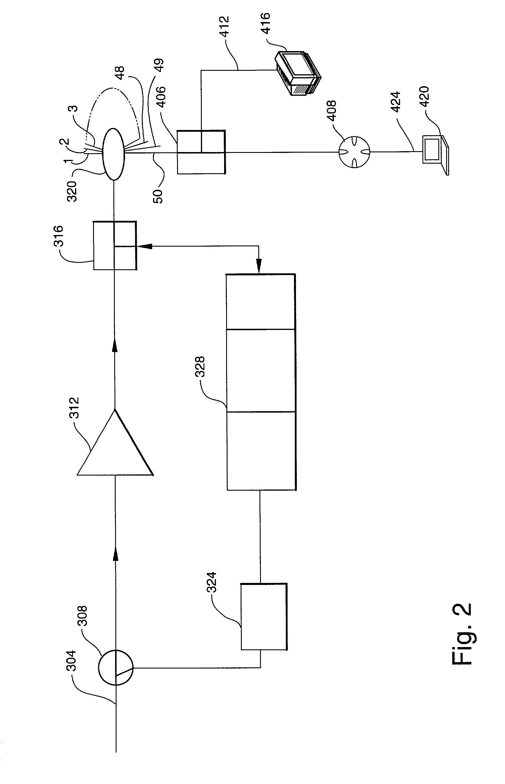
[0033] Architecture
[0034] FIG. 1 illustrates the overall architecture. FIG. 1 can be subdivided into four clusters of components. The first cluster is Cable-TV (CATV) head-end equipment 100. The second cluster is the Hybrid Fiber-coax (HFC) Distribution Network 200. The third cluster is the premises coax distribution equipment 300 which could exist in either an MDU or an analogous situation such as a hotel. The final cluster is the cluster of equipment in the user's room 400. Clusters 300 and 400 contain elements of the present invention. In keeping with industry conventions, the CATV head-end and the Internet are the upstream end of FIG. 1 for cable TV and IP data respectively. The television set or computer in the user's room are the downstream points. Upstream data transmissions travel upstream towards the upstream end. Downstream transmissions travel downstream towards the downstream end. Thus a component on a data path receives a downstream data transmission from its upstream e...
PUM
 Abstract
Description
Claims
Application Information