High speed camera based sensors

a camera and sensor technology, applied in closed circuit television systems, instruments, material analysis, etc., can solve the problems of not revealing the methods by which such devices can actually be used, limiting the versatility of sensors, and adding extra costs, etc., to achieve the highest possible operational speed, reasonable cost, and acceptable accuracy

Inactive Publication Date: 2002-05-23
LMI TECH
View PDF2 Cites 17 Cited by
  • Summary
  • Abstract
  • Description
  • Claims
  • Application Information

AI Technical Summary

Benefits of technology

[0020] It is a goal of the invention to provide a sensory device, employing at least one photo-detector array camera operating at the highest possible operational speed, with acceptable accuracy and at reasonable cost.
[0021] It is another goal of the invention to provide method and apparatus for selectively analyzing certain portions of an image in order to improve sensor response speed, and for predicting the portions to analyze in the future.
[0024] It is also a goal of the invention to provide a method for increasing the reliability of detection of projected zones on objects with variant reflectance characteristics at different portions of their surface.
[0025] It is another goal of the invention to provide method and apparatus for increasing the speed of camera based sensors in determining the location of features in an image.
[0026] It is a further goal of the invention to provide means for high speed contouring of objects, especially those moving with respect to a sensor.
[0030] FIGS. 4A-B illustrate a pixel scan and processing embodiment using rough approximations of analog pixel values to increase scan speeds.

Problems solved by technology

This allows only one scan line of potential data to be interrogated, limiting the versatility of the sensor considerably, and increasingly adding extra cost (due to the relative expense of the lower volume linear array devices).
However, this patent does not disclose methods by which such devices can actually be used to make practical triangulation or other measurements required in industry in an apparatus such as disclosed herein.

Method used


Image

  • High speed camera based sensors
  • High speed camera based sensors
  • High speed camera based sensors

Examples


Embodiment Construction

[0032] FIG. 1

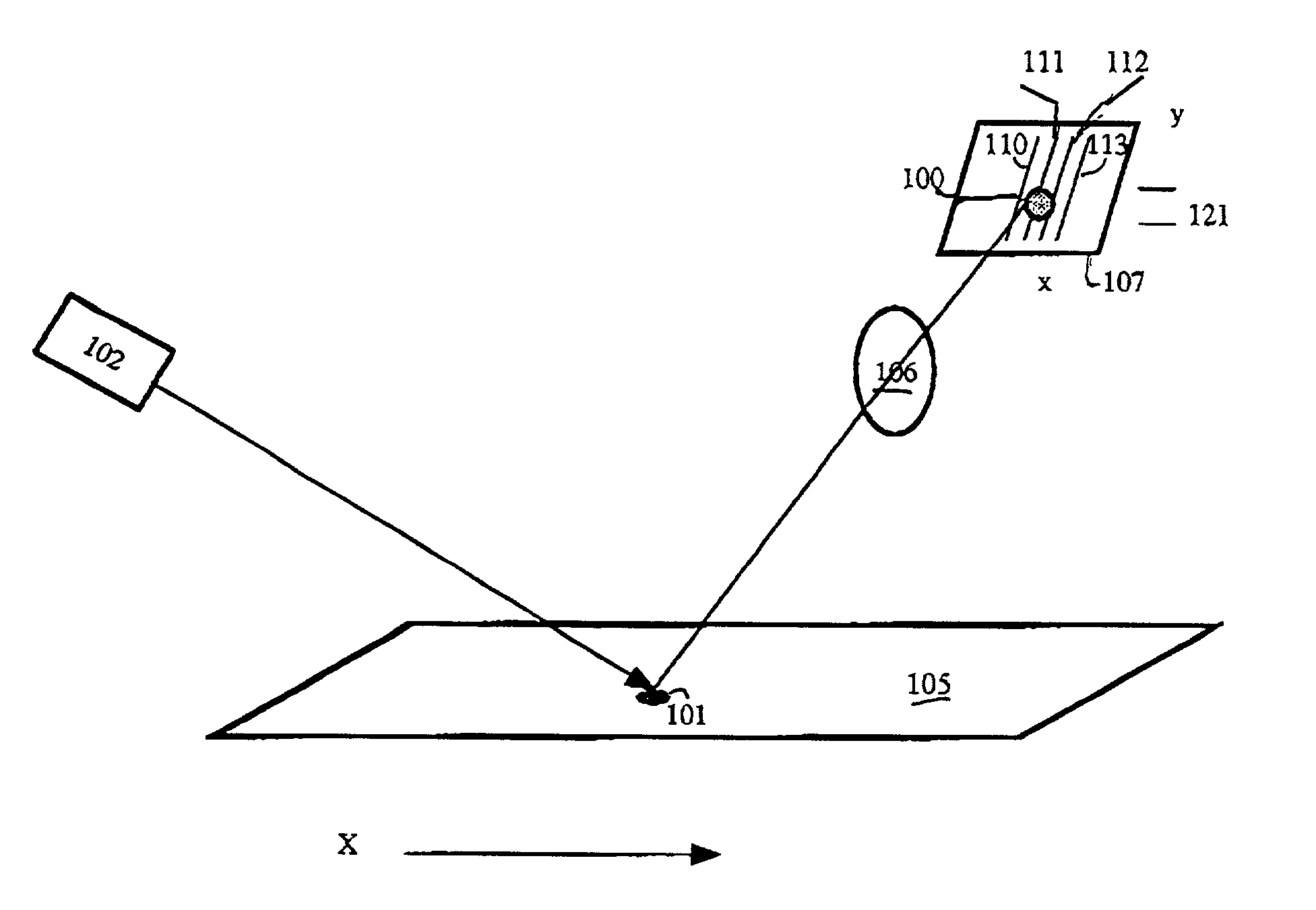
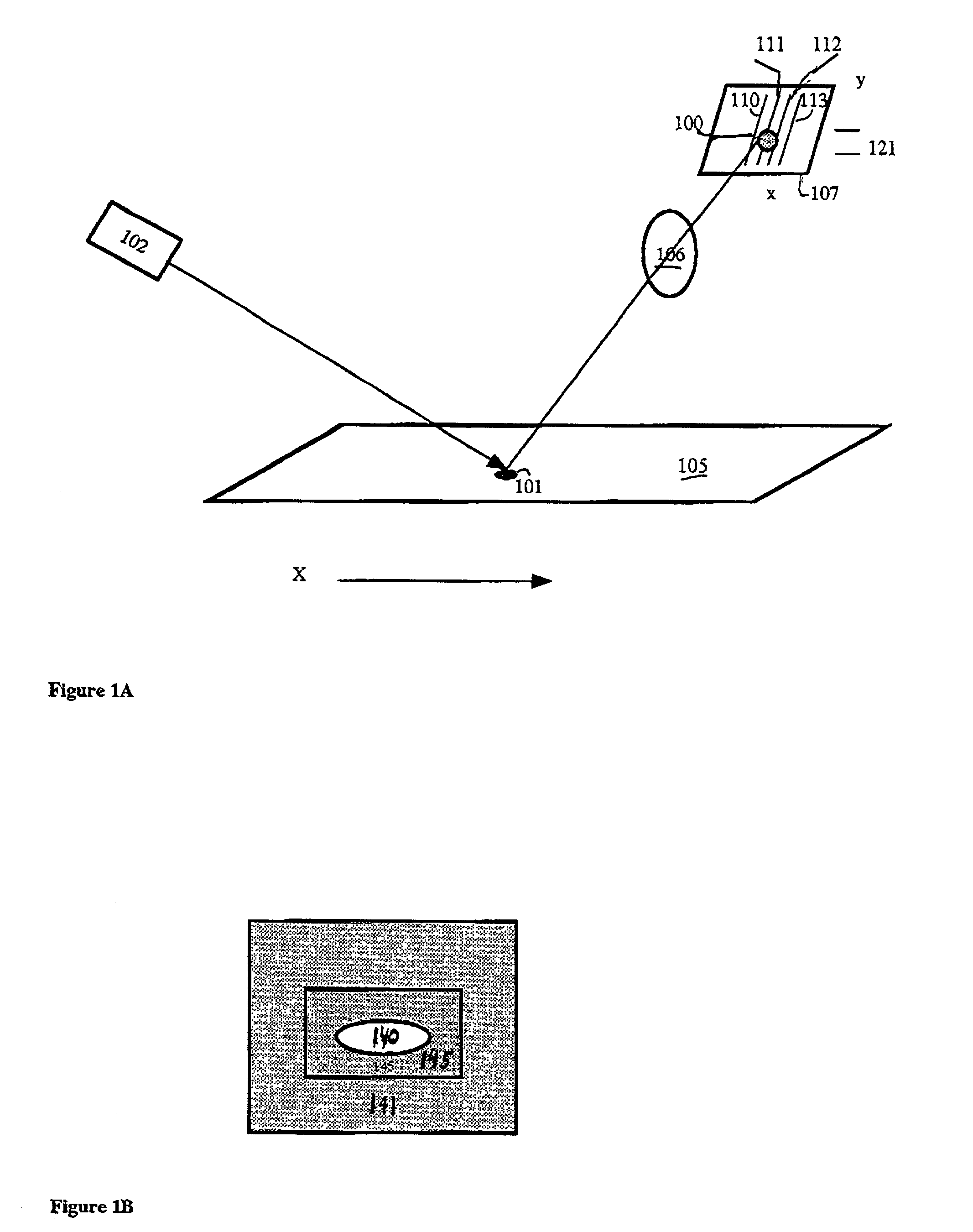
[0033] FIG. 1A illustrates triangulation sensor embodiments of the invention employing a spot shaped zone. For example, consider image 100 of a spot type projected zone 101, projected by laser 102 on object 105, which is imaged by lens 106 on to pixel addressable photo-detector matrix array 107, for example a Photon Vision Systems (Homer, N.Y.) ACS-I active column imager. It is desirable for many applications that the pixels of the array are able to be read in a non-destructive manner, such that one can re-read their values based on intelligence gathered in a first reading. Such readout is relatively common with CMOS type photo-detector arrays, such as those made by Photobit company.

[0034] Typically such sensors employ photo-detectors which are photo-detector arrays of either linear or matrix types. Processing to determine zone image position can be using thresholded centroids and multiple centroids as described Pryor et al, derivatives as described in Liptay-Wagner et ...


PUM


Abstract

Disclosed herein are TV Camera based electro-optical sensors, providing affordable methods and apparatus for high speed determination of dimensions and other features of objects. Preferred embodiments utilize addressable line or pixel based cameras to effect triangulation based and other machine vision sensing of objects.

Description

CROSS REFERENCES TO RELATED CO-PENDING APPLICATIONS[0001] This application claims benefit of U.S. Provisional Application No. 60 / 227,018.[0002] Reference is made to U.S. Ser. No. ______ "High Speed and Reliable Determination of Lumber Quality Using the Tracheid Effect", and U.S. Ser. No. ______ "Improved Method And Apparatus For Scanning Lumber And Other Objects", filed the same day, the disclosures of both of which are incorporated herein by reference.[0003] The invention relates to TV Camera based and other electro-optical sensors and systems, providing affordable methods and apparatus for high speed scanning of dimensions and other features of objects.[0004] The invention uses one or more light sources combined with TV cameras which may be randomly scanned in some form, and whose output is used as input to a computer, such as a PC. This data is analyzed to typically provide data concerning the location or dimension of objects or parts of objects and / or the presence or characteris...

Claims


Application Information

Patent Timeline
Patent Type & Authority Applications(United States)
IPC IPC(8): G01B11/00G01B11/04H04N7/18
CPCG01B11/04
Inventor METCALFE, LEONARDREUSER, CASH
Owner LMI TECH
Why Eureka
Try Eureka