Non-mold method of forming objects and articles formed thereby

Inactive Publication Date: 2002-05-23
EVANS ROBERT B
View PDF0 Cites 5 Cited by
  • Summary
  • Abstract
  • Description
  • Claims
  • Application Information

AI Technical Summary

Benefits of technology

0028] It is still another more important object of the invention to provide a method of forming modular elements using a non-mold forming process wherein menial labor is utilized for securing components together to thereby form finished articles of enhanced functional characteristics, but of relatively low-cost in terms of tools, jigs, molds, and labor.
0029] It is still another more important object of the invention to provide a non-mold forming proce

Problems solved by technology

However, the concept, in the broad sense of having inner and outer skins or

Method used


Image

  • Non-mold method of forming objects and articles formed thereby
  • Non-mold method of forming objects and articles formed thereby
  • Non-mold method of forming objects and articles formed thereby

Examples


example

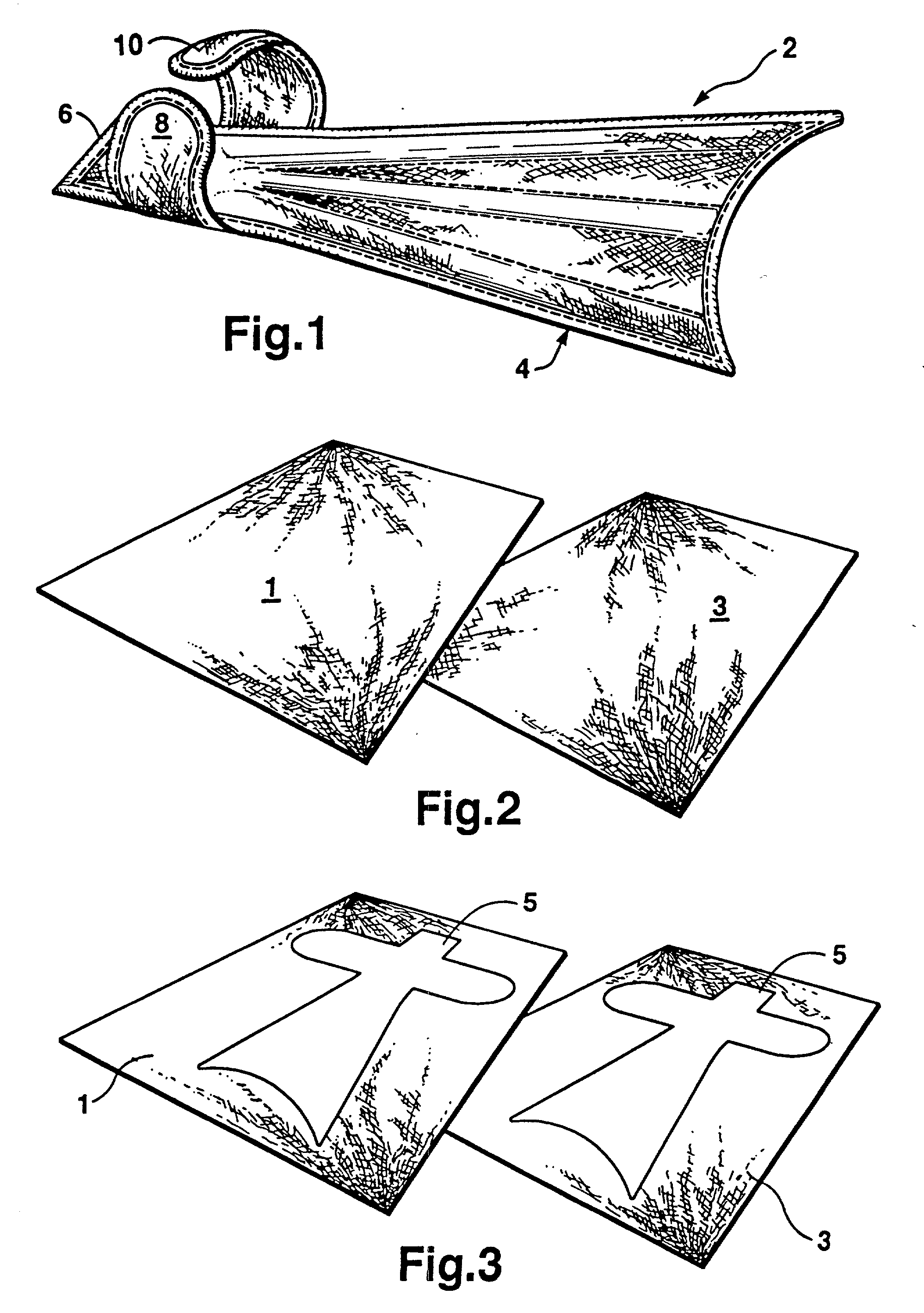
[0065] 1. Two sheets of polyurethane-backed nylon cloth are cut according to the fin pattern shape illustrated in FIGS. 2-4.

[0066] 2. A sheet of nylon mesh is cut according to the same fin pattern shape.

[0067] 3. The nylon mesh is positioned between two sheets of polyurethane-backed nylon cloth with the polyurethane backing on the inside (toward the mesh).

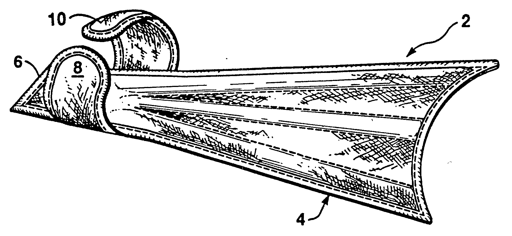
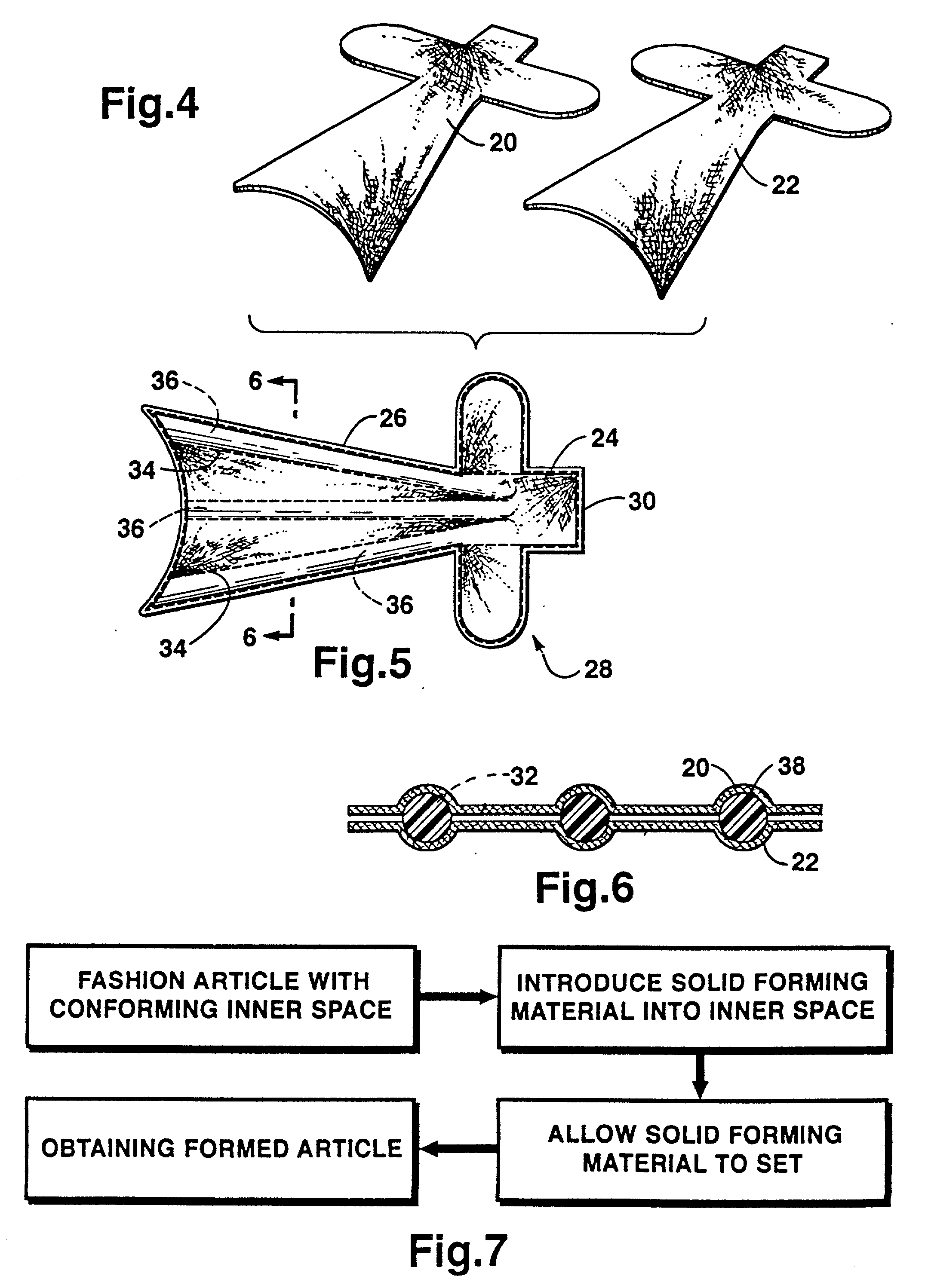
[0068] 4. The three pieces are sewn together to form the shape of the fin and cavities as shown in FIG. 5. The edge cavities are sewn to form a cavity or inner space whose cross section starts at one inch at the foot pocket side of the blade and shrinks to one-half inch at the tip of the blade. The center cavity also narrows from one inch to one-half inch, but it only extends half way from the foot pocket to the end of the blade. The cavities extend to the heel of the foot pocket base to form an opening to pour thermoset polyurethane into. The opening extends a minimum of two inches from where the edge of the final product is to be...


PUM


Abstract

This invention relates to a non-mold method of forming articles and to the articles themselves wherein various configured articles may be fashioned with conformable material which may be easily fabricated as by sewing, or heat, or sonic welding to form the basic shape of or modular elements of a completed article, and wherein a thermal setting, flowable polymer or the like is introduced into the space between layers of the conformable material to thereby form the completed article or modular element.

Description

RELATION TO OTHER APPLICATIONS[0001] This is a continuation-in-part application of divisional application Ser. No. 09 / 887,451 which is a divisional application of of U.S. patent application Ser. No. 09 / 466,657 now U.S. Pat. No. 6,283,810, which in turn is a continuation-in-part application of U.S. patent application in the name of the same inventor entitled NON-MOLD METHOD OF FORMING OBJECTS AND ARTICLES FORMED THEREBY, application Ser. No. 09 / 195,596 having a filing date of Nov. 18, 1998, now U.S. Pat. No. 6,241,567 B1.[0002] This invention relates to a non-mold method of forming articles and to the articles themselves wherein various configured articles may be fashioned with conformable material which may be easily fabricated as by sewing, or heat, or sonic or radio frequency welding to form the basic shape of or modular elements of a completed article, and wherein a thermal setting, flowable plastic or the like is introduced into the space between layers of the conformable materi...

Claims


Application Information

Patent Timeline
IPC IPC(8): A63B31/10B29C39/12B29C70/74
CPCA63B31/10A63B2209/00B29K2105/0002B29C70/745B29C39/126Y10T428/249999
Inventor EVANS, ROBERT B.
Owner EVANS ROBERT B
Why Eureka
Try Eureka