Flat-type fluorescent lamp for illumination unit and liquid crystal device

a fluorescent lamp and illumination unit technology, applied in the field of flat-type fluorescent lamps, can solve the problems of unfavorable edge-light backlight, difficulty in efficiently and uniformly guiding light from fluorescent lamps to the rear surface of the panel, and increase difficulty

Inactive Publication Date: 2002-05-30
VISTA PEAK VENTURES LLC
View PDF0 Cites 25 Cited by
  • Summary
  • Abstract
  • Description
  • Claims
  • Application Information

AI Technical Summary

Problems solved by technology

First, the light from the fluorescent lamp is difficult to be guided to the rear surface of the panel efficiently and uniformly. This difficulty increases with the widening display area of LCD devices.
Second, since the fluorescent lamp is located in the picture-frame area of LCD devices, the edge-light type backlight is unfavorable from the viewpoint of narrowing the picture-frame area.
If the lamps are located too close to the panel, the light from the lamps is locally illuminated to the rear surface of the panel, which means that the light has uneven brightness.
Thus, the direct-type backlight has a disadvantage that it is difficult to cope with the requirement of thinning LCD devices.
First, the ends of the cables 113 are connected to the electrode terminals 107 and then, the cables 113 are placed to run through the inner space that is located outside the frame member 103 and that intervenes between the plates 101 and 102. Thereafter, the cables 113 are collected at the cable window 117 and taken out of the space through the window 117 to the rear side of the LCD device. The outer ends of the cables 117 are connected to the circuit board 112 on the rear side of the device. Thus, there is a problem that wiring, connection, and assembly operations of the device are troublesome and that the necessary length of the cables 113 is large.
Second, since the cable wi

Method used


Image

  • Flat-type fluorescent lamp for illumination unit and liquid crystal device
  • Flat-type fluorescent lamp for illumination unit and liquid crystal device
  • Flat-type fluorescent lamp for illumination unit and liquid crystal device

Examples


first embodiment

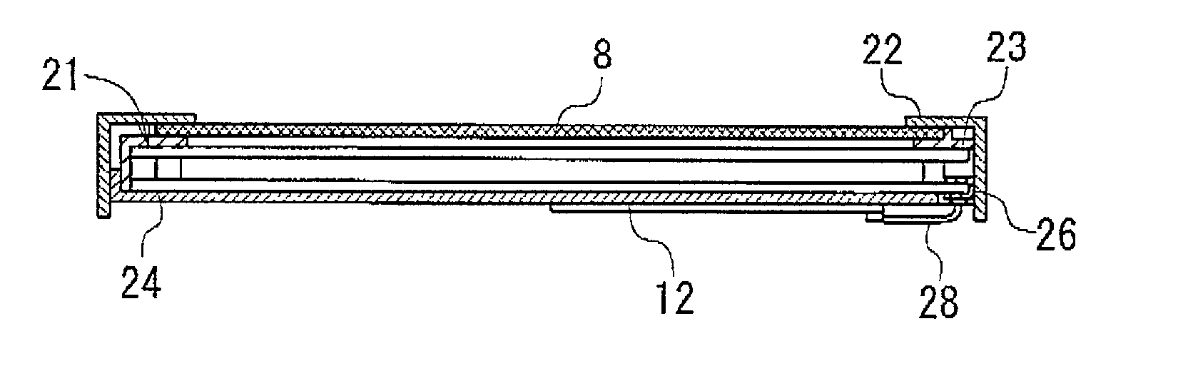
[0139] FIGS. 3A and 3B show a LCD device according to the invention, which comprises a LCD panel 8, a flat-type fluorescent lamp 21 as the backlight, a rectangular front chassi 22, a rectangular center chassi 23, and a rectangular rear chassi 24.

[0140] The flat-type fluorescent lamp 21 comprises a rectangular emission-side plate 1, a rectangular electrode-side plate 2, and a rectangular frame member 3 that intervenes between the plates 1 and 2. The plates 1 and 2 are entirely overlapped with each other by way of the member 3 in such a way that the contour of the Plate 1 accords with that of the plate 2. The rectangular outer edges (peripheral areas) of the plates 1 and 2 are placed outside the member 3. Electrodes 4 are formed on the inner surface of the plate 2 by a screen printing method or the like. The ends of part of the electrodes 4 are extended to the outside of the member 3 on the inner surface of the plate 2, forming four electrode terminals 7 (i.e., two anode terminals and...

second embodiment

[0162] FIGS. 5, 6A and 6B show a LCD device according to a second embodiment of the invention, which comprises the LCD panel 8, a flat-type fluorescent lamp 31 as the backlight, a rectangular front chassi 32, a rectangular center chassi 33, and a rectangular rear chassi 34.

[0163] The flat-type fluorescent lamp 31 comprises a rectangular emission-side plate 35, a rectangular electrode-side plate 36, and a rectangular frame member 3 that intervenes between the plates 35 and 36. The plates 35 and 36 are entirely overlapped with each other by way of the member 3 in such a way that the contour of the plate 35 accords with that of the plate 36. Unlike the first embodiment, the rectangular contours of the plates 35 and 36 accord with rectangular contour of the member 3. In other words, the outer edges of the plates 35 and 36 are not located outside the member 3. Thus, the outer side faces of the member 3 are approximately in the same planes as those of the corresponding outer side faces of...

third embodiment

[0187] FIGS. 7A and 7B show a LCD device according to a third embodiment of the invention, which has substantially the same configuration as the LCD device of the second embodiment of FIGS. 5, 6A and 6B, except that the electrode-side plate 36 has a rectangular recess 41 at the position where the inner arm of the U-shaped electrode 40 is placed, and that the inner arm is received in the recess 41. Therefore, the detailed explanation is omitted here for simplification by attaching the same reference symbols as those used in the second embodiment in FIGS. 7A and 7B.

[0188] Specifically, as shown in FIGS. 7A and 7B, the rectangular recess 41 is formed on the inner surface of the plate 36 at the position where the inner arm of the U-shaped electrode 40 is attached. The recess 41 extends inwardly from the side edge of the plate 36 at a specific length. The electrode terminal 37 is located on the bottom of the recess 41. The inner end of the U-shaped electrode 40 is entirely buried in the ...


PUM


Abstract

A flat-type fluorescent lamp for LCD devices is provided, which makes it possible to narrow the picture-frame area and to widen the emission area and which facilitates their wiring, connection and assembly operations. The lamp comprises: (a) a container having a first plate, a second plate, and a frame member; the first and second plates being opposed to each other and fixed together with the frame member in such a way as to have a specific distance between the first and second plates; the first plate forming a flat emission surface; (b) a gaseous substance confined in the container; (c) a fluorescent material layer formed on an inner surface of the container; (d) electrodes formed on an inner surface of the second plate; and (e) a conductor member attached to the second plate in such a way as to extend along the inner surface of the second plate and an outer edge face thereof; a first end of the conductor member being contacted with a terminal part of the electrodes; a second end of the conductor member being located outside the second plate.

Description

[0001] 1. Field of the Invention[0002] The present invention relates to a flat-type fluorescent lamp with a flat emission surface. More particularly, the invention relates to a flat-type fluorescent lamp, an illumination unit using the lamp, and a Liquid-Crystal Display (LCD) device equipped with the lamp as its backlight, which make it possible to narrow the frame area of a LCD device and to widen its display area.[0003] 2. Description of the Related Art[0004] Conventionally, illumination units are used to form the edge-type or direct-type backlights of LCD devices.[0005] With the edge-light type backlight, a cylindrical fluorescent lamp is located apart from a LCD panel to extend along one edge of the panel. The lamp is not overlapped with the rear surface of the panel. A light guide plate, which is made of acrylic resin, is provided near the fluorescent lamp to guide the light from the lamp toward the rear of the panel. A diffuser sheet is provided near the light guide plate to d...

Claims


Application Information

Patent Timeline
IPC IPC(8): G02F1/1335G02F1/1333G02F1/13357H01J61/30H01J61/36
CPCG02F1/133604H01J61/305G02F2001/133612G02F1/133608G02F1/133612G02F1/1335
Inventor OISHI, TOSHIYAFUJISHIRO, FUMIHIKOKANATSU, TSUTOMU
Owner VISTA PEAK VENTURES LLC
Why Eureka
Try Eureka