

Roll changing apparatus and roll changing method for rolling mill
a technology of rolling mill and changing apparatus, which is applied in mechanical equipment, auxiliaries, manufacturing tools, etc., can solve the problems of high fixture cost, complicated and upsized structure, and labor and time consuming
- Summary
- Abstract
- Description
- Claims
- Application Information
AI Technical Summary
Benefits of technology
Problems solved by technology
Method used
Image

Examples
first embodiment
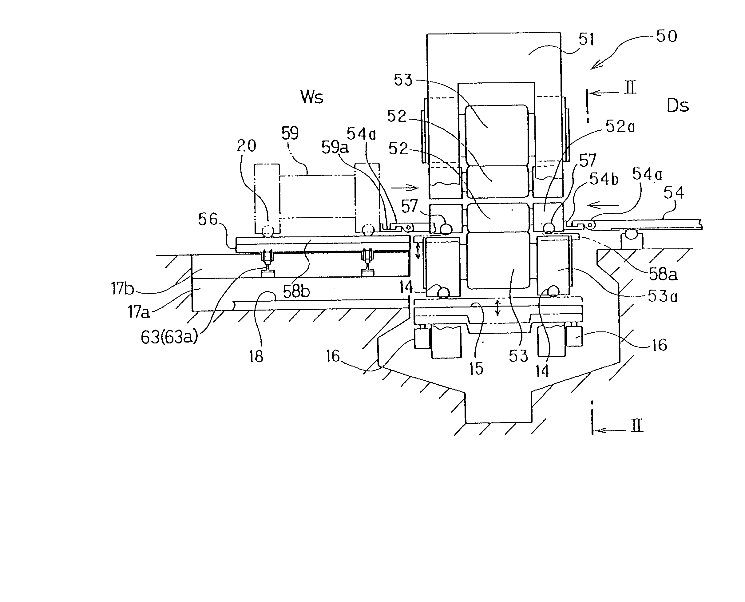
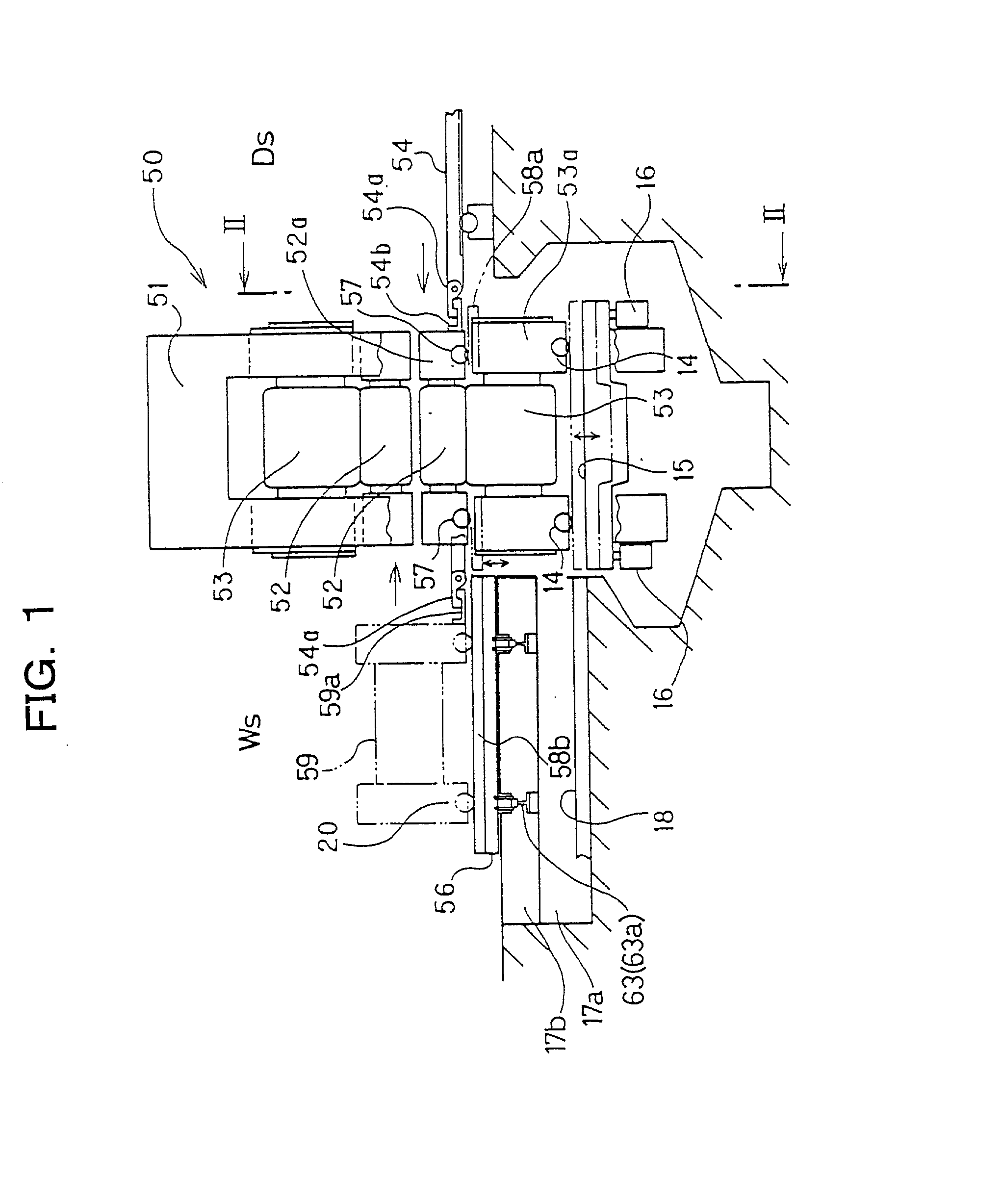
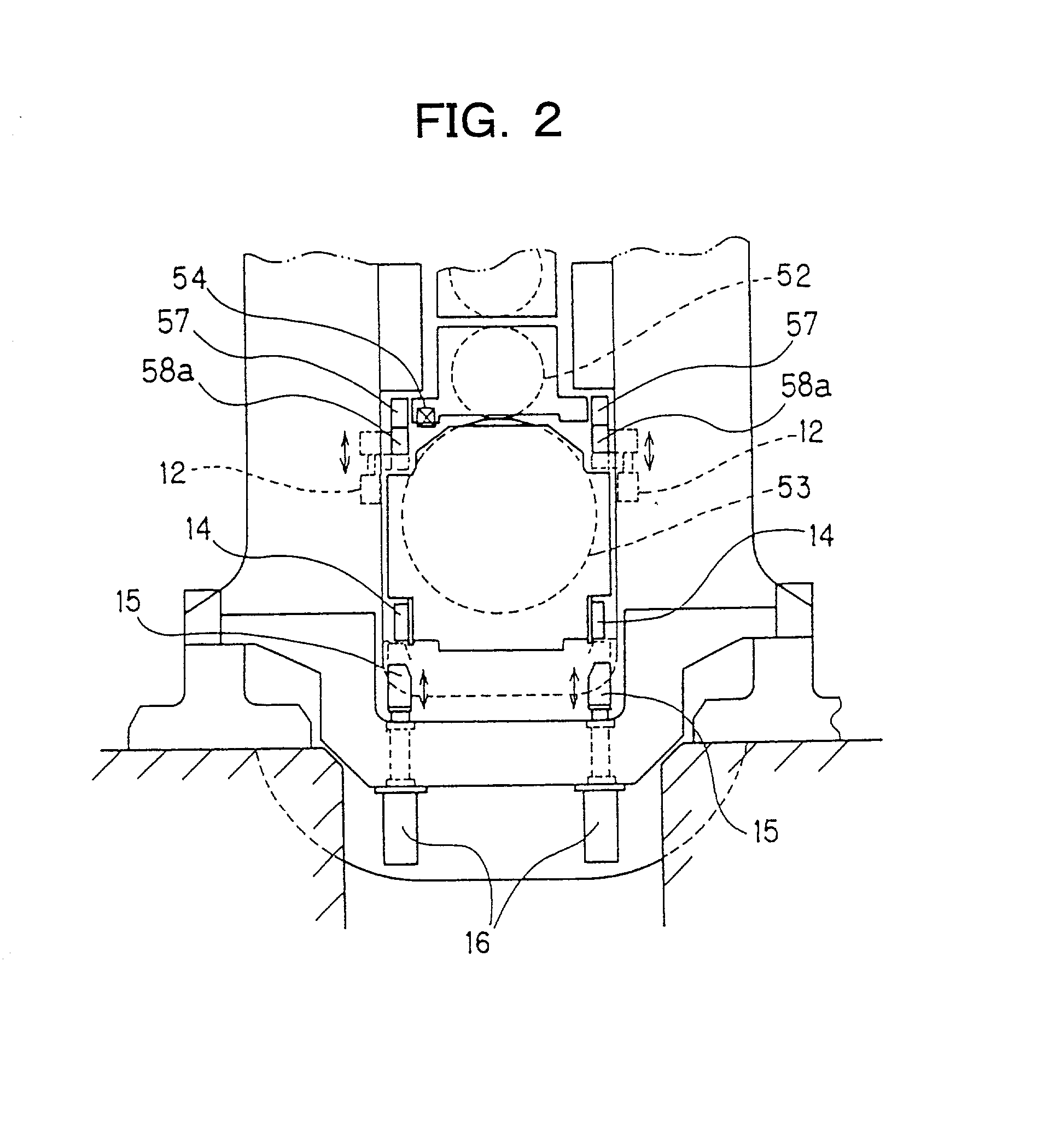
[0081] FIG. 1 is a front view of a four-high rolling mill according to the present invention. FIG. 2 is a view taken on line II-II in FIG. 1. FIGS. 3(A) to 3(C) are explanation drawings of a roll changing procedure for the four-high rolling mill. In these drawings, the same members as in FIGS. 16 and 17 are assigned the same numerals, and duplicate explanations are omitted.
[0082] As shown in FIGS. 1 and 2, a conventional pusher 54 disposed on a drive side Ds of a rolling mill stand 51 serves to push out and pull in upper and lower work rolls 52 as a pair and upper and lower backup rolls 53 as a pair, and the lower backup roll 53 and a stool 59 for roll changing are provided with wheels. In this manner, a roll changing apparatus of a four-high rolling mill 50 is constituted in the present invention.
[0083] In the drawings, the numeral 12 denotes a drive cylinder for raising and lowering an up-and-down rail 58a in the rolling mill stand 51, 14 denotes a wheel provided on a lower backup...
second embodiment
[0094] FIG. 4 is a front view of a four-high rolling mill according to a second embodiment of the present invention. FIG. 5 is a view taken on line V-V in FIG. 4. FIGS. 6(A) to 6(D) are explanation drawings of a roll changing procedure for the four-high rolling mill.
[0095] This embodiment is designed such that the roll changing stool is a conventional type without wheels, a connecting portion for connection with a pusher is provided at the upper end of a wheeled lower backup roll chock, a lower backup roll is supported on up-and-down rails within a rolling mill stand, the lower backup roll is raised to a height at which the lower backup roll is connectable with the pusher for changing of the backup rolls, the lower backup roll at the raised position is pushed out and pulled in between the inside of the rolling mill stand and rails on the work side by the pusher, and the single pusher serves for both of changing of the work rolls and changing of the backup rolls.
[0096] As shown in FI...
third embodiment
[0104] FIG. 7 is a side view of a roll changing apparatus according to a third embodiment of the present invention. FIG. 8 is a view taken on line VII-VII in FIG. 7. FIG. 9 is an operating state view during work roll changing by the roll changing apparatus. FIG. 10 is an operating state view during backup roll changing by the roll changing apparatus.
[0105] In FIGS. 7 and 8, C denotes a roll pullout center position of a rolling mill viewed from its side, 11 denotes a work roll assembly to be replaced, 17a denotes a backup roll pulling-out pit formed on the work side in alignment with the position of the rolling mill, and 17b denotes a channel-shaped pit for roll changing apparatus installation formed on the work side Ws of the rolling mill.
[0106] The present roll changing apparatus includes rails (floor rail portion) 63 laid on the channel-shaped pits 17b located ahead of and behind the backup roll pulling-out pit 17a dividedly in the shifting direction, i.e., discontinuously so as n...
PUM
| Property | Measurement | Unit |
|---|---|---|
| Length | aaaaa | aaaaa |
| Height | aaaaa | aaaaa |
Abstract
Description
Claims
Application Information