Heating head for soldering and de-soldering of SMD components

a heat transfer head and soldering head technology, applied in the direction of non-electric welding apparatus, manufacturing tools, solventing apparatus, etc., can solve the problem of limiting heat transfer to the handl

Inactive Publication Date: 2002-07-04
RUSZOWSKI CZESLAW A
View PDF22 Cites 27 Cited by
  • Summary
  • Abstract
  • Description
  • Claims
  • Application Information

AI Technical Summary

Problems solved by technology

The heater sub-assembly is held to the handle via an insulation ring, which also limits heat transfer to the handle.

Method used


Image

  • Heating head for soldering and de-soldering of SMD components
  • Heating head for soldering and de-soldering of SMD components
  • Heating head for soldering and de-soldering of SMD components

Examples


Embodiment Construction

[0053] The following detailed description is of the best mode or modes of the invention presently contemplated. Such description is not intended to be understood in a limiting sense, but to be an example of the invention presented solely for illustration thereof, and by reference to which in connection with the following description and the accompanying drawings one skilled in the art may be advised of the advantages and construction of the invention.

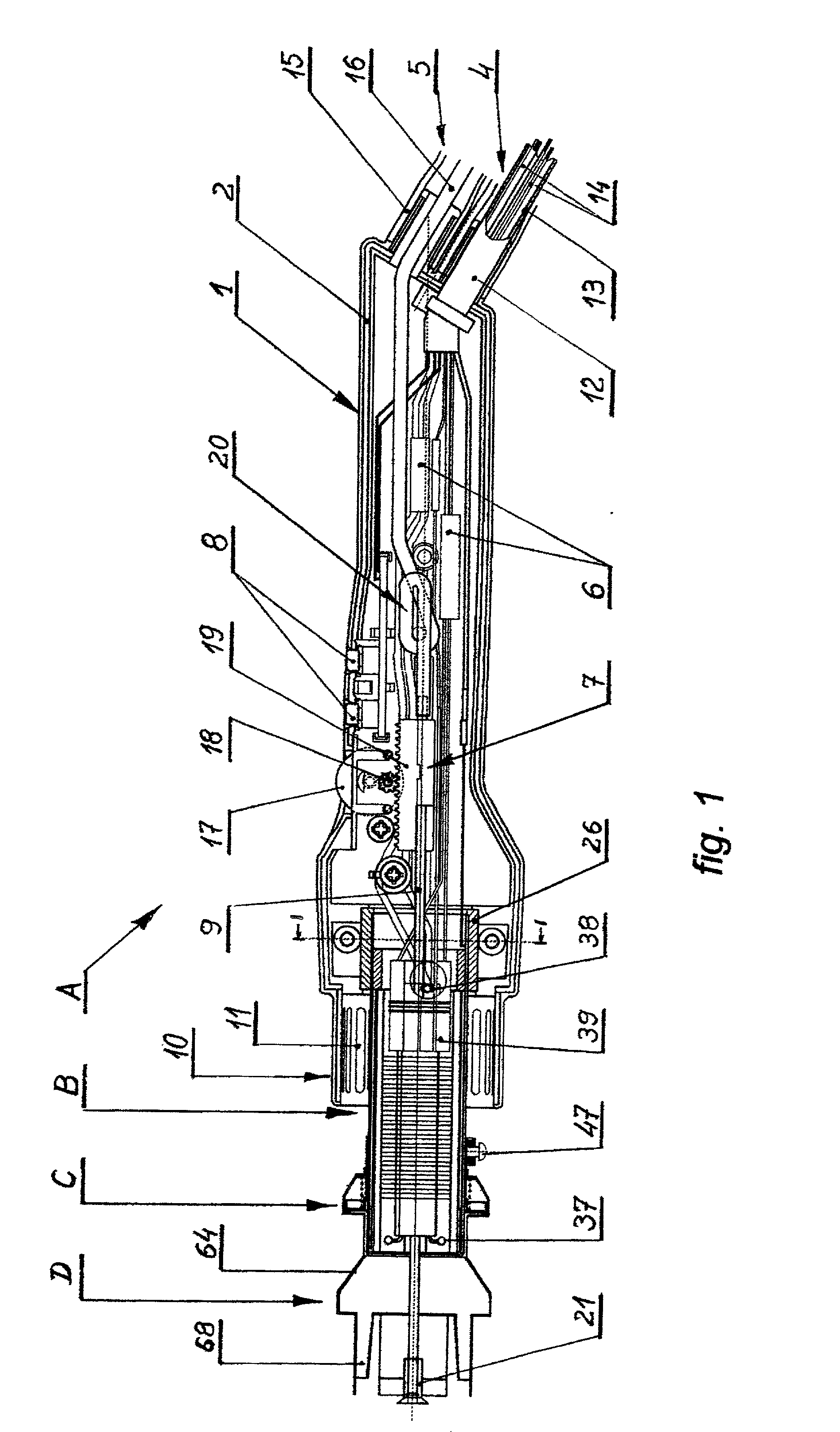
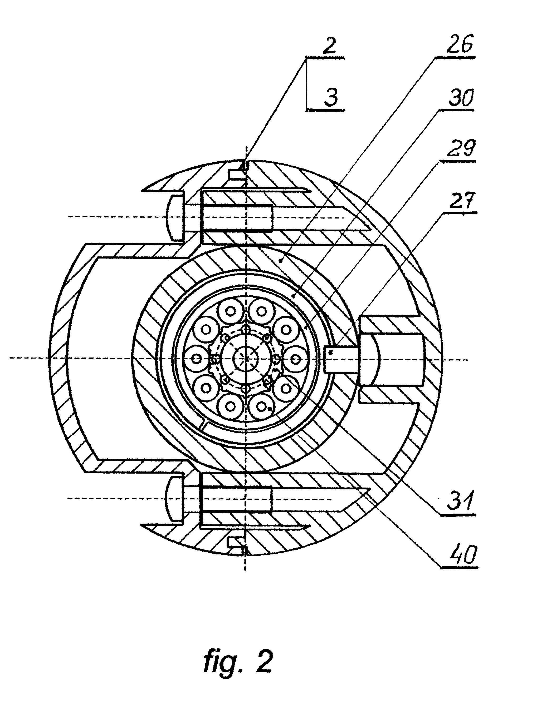
[0054] The heating head for soldering and de-soldering of SMD surface mounted devices of the present invention, shown in cross-section in FIG. 1, is comprised of a handle portion A having mounted on its forward end heater subsystem B, to which nozzle quick connect mechanism C is mounted, and with heating nozzle D connected via such quick connect mechanism. The components of handle portion A are enclosed in housing 1, which is made of high temperature, static dissipative plastic. As shown in FIG. 2, housing 1 is comprised of two parts di...


PUM

PropertyMeasurementUnit
flexibleaaaaaaaaaa
shapeaaaaaaaaaa
thermal resistantaaaaaaaaaa

Abstract

A heating head for soldering and de-soldering surface mount devices (SMD's) using hot inert gas or air is comprised of a handle in which there is placed a heater sub-assembly on which there is secured a quick connect mechanism for mounting a heating nozzle. The heater sub-assembly is enclosed in a shroud and is secured to the end of the handle by a thermal insulating ring, such shroud housing a ceramic rod having elongated bosses on which a heating element is secured, while a laminar flow equilizer is used to provide more uniform gas flow across the heating element. Quick connect mechanism is secured to the heater sub-assembly shroud and uses a spring loaded winged locking mechanism to the secure heating nozzles to the heater head. In one embodiment, the heating nozzles have a truncated pyramid shaped chamber to which individual end nozzles made by folding a flat, thin sheet metal pattern are attached for directing gas flow, while in another embodiment a chamber having a centrally located circulation hole on the side walls and further circulation hole at the bottom edge of the each side wall near the corners of the chamber is provided.

Description

CROSS REFERENCE TO RELATED APPLICATIONS[0001] Applicant claims benefit to Polish Patent No. W-111548 filed on Nov. 13, 2000 and Polish Patent No. W-111661 filed on Dec. 12, 2000, both of which are hereby incorporated by reference.BACKGROUND OF THE INVENTION[0002] 1. Field of the Invention[0003] The present invention relates generally to soldering and desoldering of SMD components, and more specifically to a heating device having a novel hot gas flow arrangement, nozzle attachment mechanism, and end nozzle design for soldering and desoldering solid state devices through utilization of a stream of hot neutral gas.[0004] 2. Description of the Prior Art[0005] The subject of this patent is a heating head for soldering and de-soldering of SMD components using a hot neutral gas or air stream.[0006] Numerous hot gas type soldering / desoldering machines are known for attaching and removing electronic components from a printed circuit board (PCB). One known solution is described by Polish Pate...

Claims


Application Information

Patent Timeline
Patent Type & Authority Applications(United States)
IPC IPC(8): B23K1/018B23K3/047
CPCB23K1/018B23K3/0471B23K3/047
Inventor RUSZOWSKI, CZESLAW A.
Owner RUSZOWSKI CZESLAW A
Why Eureka
Try Eureka