Parking brake actuating device for a parking brake arrangement in a motor vehicle

a technology for parking brakes and actuating devices, which is applied in mechanical devices, braking systems, transportation and packaging, etc., can solve the problems of disadvantageously affecting the application of a particular embodiment form, maintenance or repair of the parking brake actuating device requires time-consuming and cost-intensive labor, and does not have a standard transmission

Inactive Publication Date: 2002-07-18
ZF FRIEDRICHSHAFEN AG
View PDF0 Cites 37 Cited by
  • Summary
  • Abstract
  • Description
  • Claims
  • Application Information

AI Technical Summary

Benefits of technology

[0012] It is further advantageous that the flange component part is arranged so as to be stationary with respect to a housing of the parking brake arrangement. The position of the parking brake actuating device relative to a blocking member and counter-blocking member of the parking brake arrangement is accordingly defined and a reliable operation of the parking brake arrangement is ensured.
[0033] The construction according to the invention makes it possible for the rotary lever arrangement to be preassembled as a constructional unit and to be positioned in operative connection to the blocking member from the outside through the through-opening of the housing. In this way, a considerable simplification is achieved compared with the assembly of a known parking brake actuating device.

Problems solved by technology

As a rule, these vehicles do not have a standard transmission because the electric engine which is provided for driving can deliver a usable torque over an appreciably broader range of speeds in any driving situation compared to an internal combustion engine.
Therefore, maintenance or repair of the parking brake actuating device requires time-intensive and cost-intensive labor.
Another disadvantageous feature is the locking arrangement which is in an operative connection with the parking brake actuating device.
This feature also disadvantageously impedes application of a particular embodiment form of the above-mentioned type of parking brake actuating device to different types of vehicles, for example, vehicles of a platform.

Method used


Image

  • Parking brake actuating device for a parking brake arrangement in a motor vehicle
  • Parking brake actuating device for a parking brake arrangement in a motor vehicle
  • Parking brake actuating device for a parking brake arrangement in a motor vehicle

Examples


Embodiment Construction

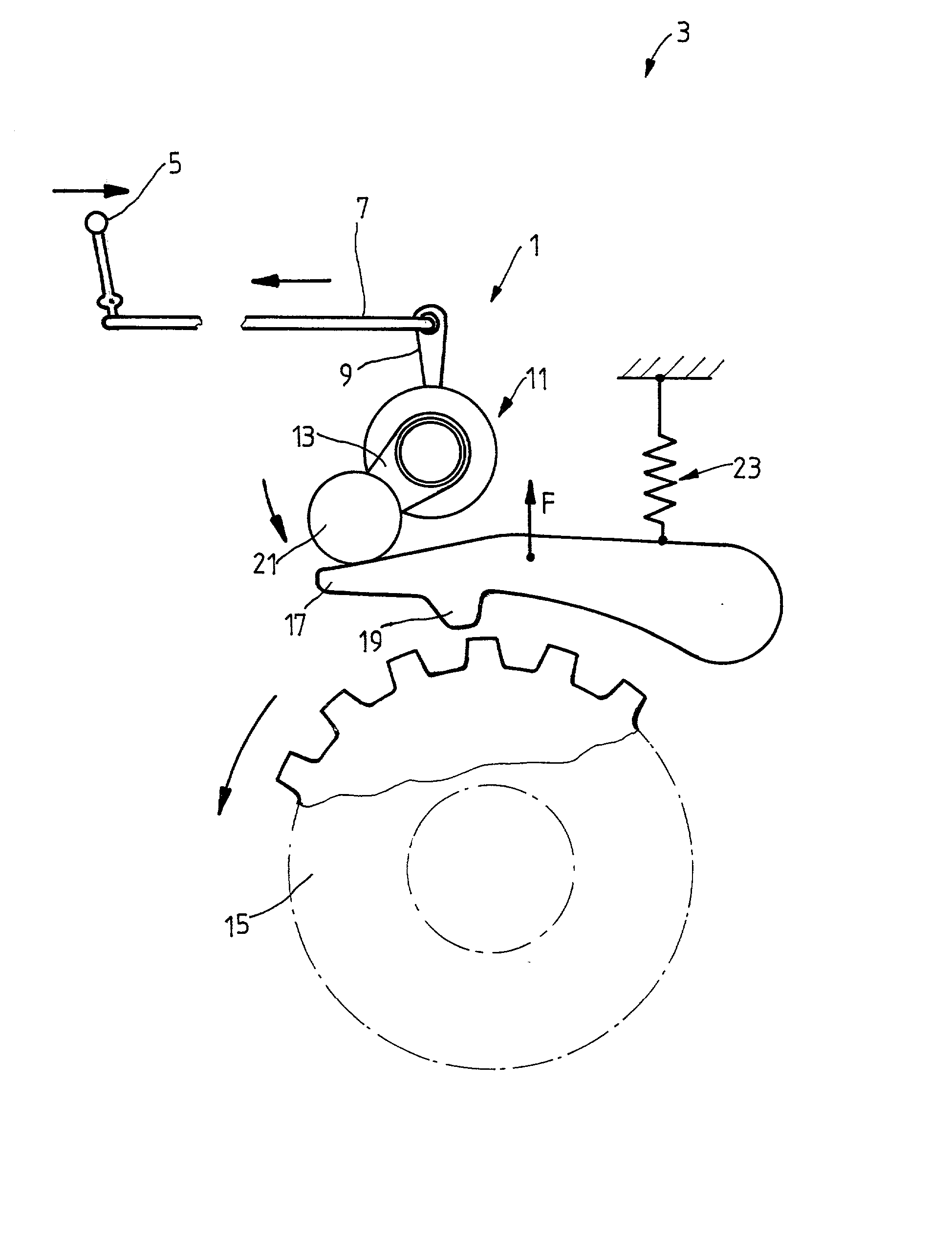
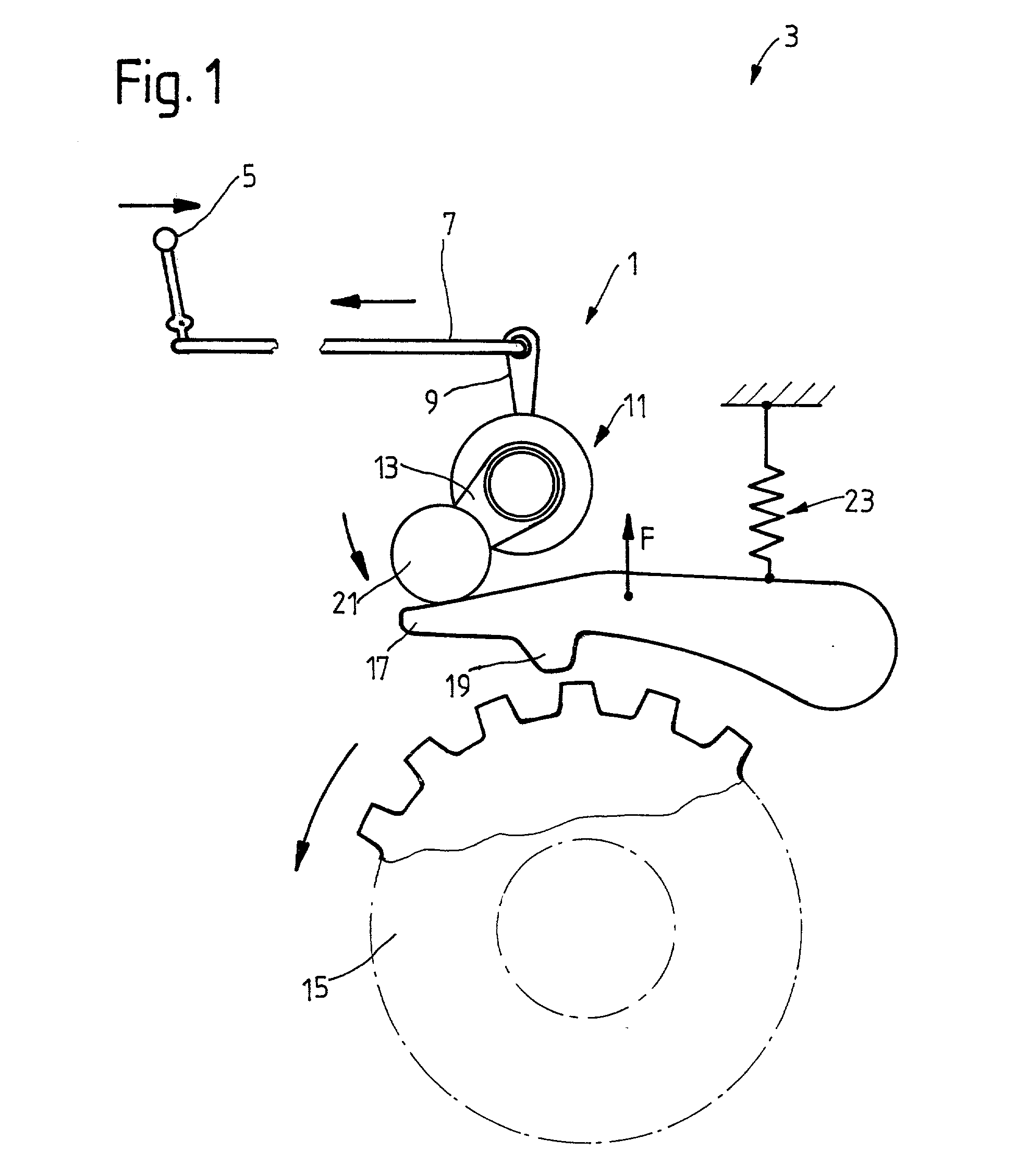
[0042] FIG. 1 shows a parking brake actuating device 1, by way of example, in a parking brake arrangement 3 in a motor vehicle. When a driver moves the selector device 5 into a parking position, an actuating force is transmitted by means of a transmission element 7, in this case, a mechanism, to an input part 9 of a rotary lever arrangement 11, wherein a torque is generated at the latter. The rotary lever arrangement 11 further has a rotary lever output part 13. The object of the rotary lever arrangement 11 is to further convey the torque introduced via the rotary lever input part 9 to the rotary lever output part 13, wherein the rotary lever output part 13 executes a rotational movement only when a counter-force F which is dependent on the position of a blocking member relative to a counter-blocking member of the parking brake arrangement 3 is overcome. In the example, the blocking member is a toothed parking brake wheel 15 and the counter-blocking member is a pawl 17 which is moun...


PUM


Abstract

A parking brake actuating device includes a rotary lever arrangement in operative connection with a compensation device providing an idle path and a restoring element for controlling the rotary lever arrangement. The rotary lever arrangement controls the engagement of a blocking member with a counter-blocking member of the parking brake arrangement. The rotary lever arrangement has a rotary lever input part and a rotary lever output part and the idle path of the compensation device can be constructed so as to be in an operative connection between the rotary lever input part and the rotary lever output part.

Description

[0001] 1. Field of the Invention[0002] The invention is directed to a parking brake actuating device for a parking brake arrangement in a motor vehicle, the device comprising a rotary lever arrangement in operative connection with a compensation device providing an idle path and a restoring element for controlling the rotary lever arrangement, which in turn can tools the engagement of a blocking member with a counter-blocking member of the parking brake arrangement.[0003] 2. Description of the Related Art[0004] Parking brake arrangements are known in general in vehicles with hydrodynamic torque converters and serve to prevent the vehicle from rolling away accidentally when the engine is turned off by blocking the transmission output shaft which is connected with the driving wheels so as to be fixed with respect to rotation relative to them. Parking brake arrangements are also applied in electrically driven motor vehicles. As a rule, these vehicles do not have a standard transmission...

Claims


Application Information

Patent Timeline
Patent Type & Authority Applications(United States)
IPC IPC(8): B60T1/06B60T1/00B60T7/08F16D63/00F16H63/34
CPCB60T1/005F16H63/3416
Inventor OPPITZ, HORSTBENKERT, STEPHAN
Owner ZF FRIEDRICHSHAFEN AG
Why Eureka
Try Eureka