Gas retarded blowback operating system for pistols and other short barreled weapons

Inactive Publication Date: 2002-07-25
NETWORK CUSTOM GUNS
View PDF0 Cites 18 Cited by
  • Summary
  • Abstract
  • Description
  • Claims
  • Application Information

AI Technical Summary

Benefits of technology

0002] The present invention provides for more accurate fire and for lower cost manufacture for semiautomatic pistols and other short barreled weapons firing high powered cartridges. Unlik

Problems solved by technology

The required clearances between the interfacing moveable parts and the motion of the parts during firing contributes to reduction in accuracy of the wea

Method used


Image

  • Gas retarded blowback operating system for pistols and other short barreled weapons
  • Gas retarded blowback operating system for pistols and other short barreled weapons
  • Gas retarded blowback operating system for pistols and other short barreled weapons

Examples


Embodiment Construction

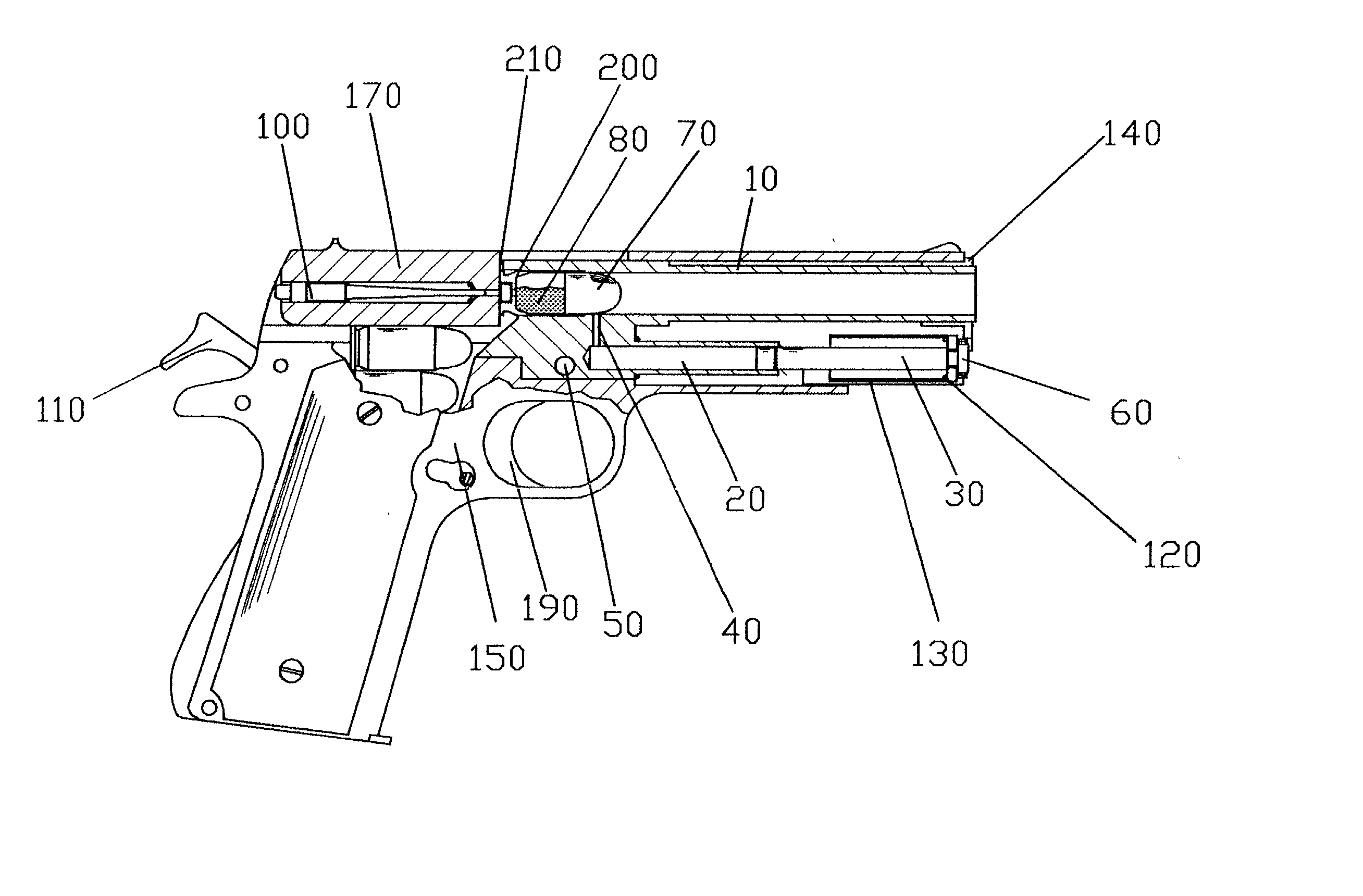
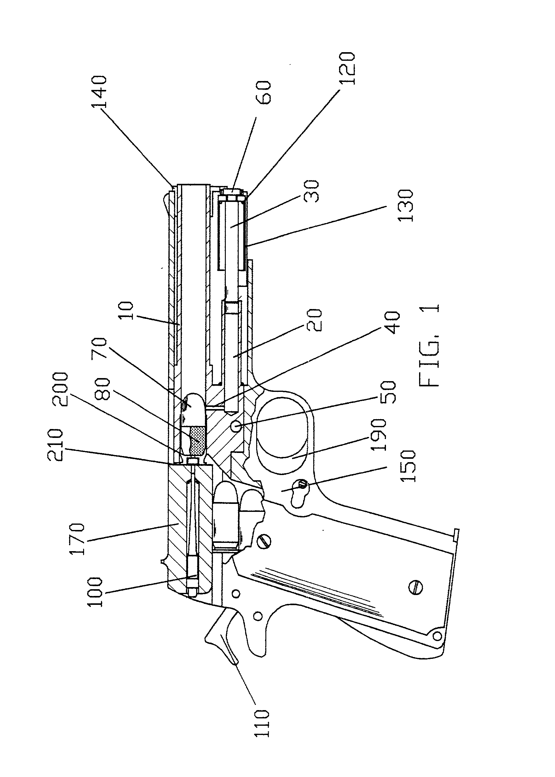
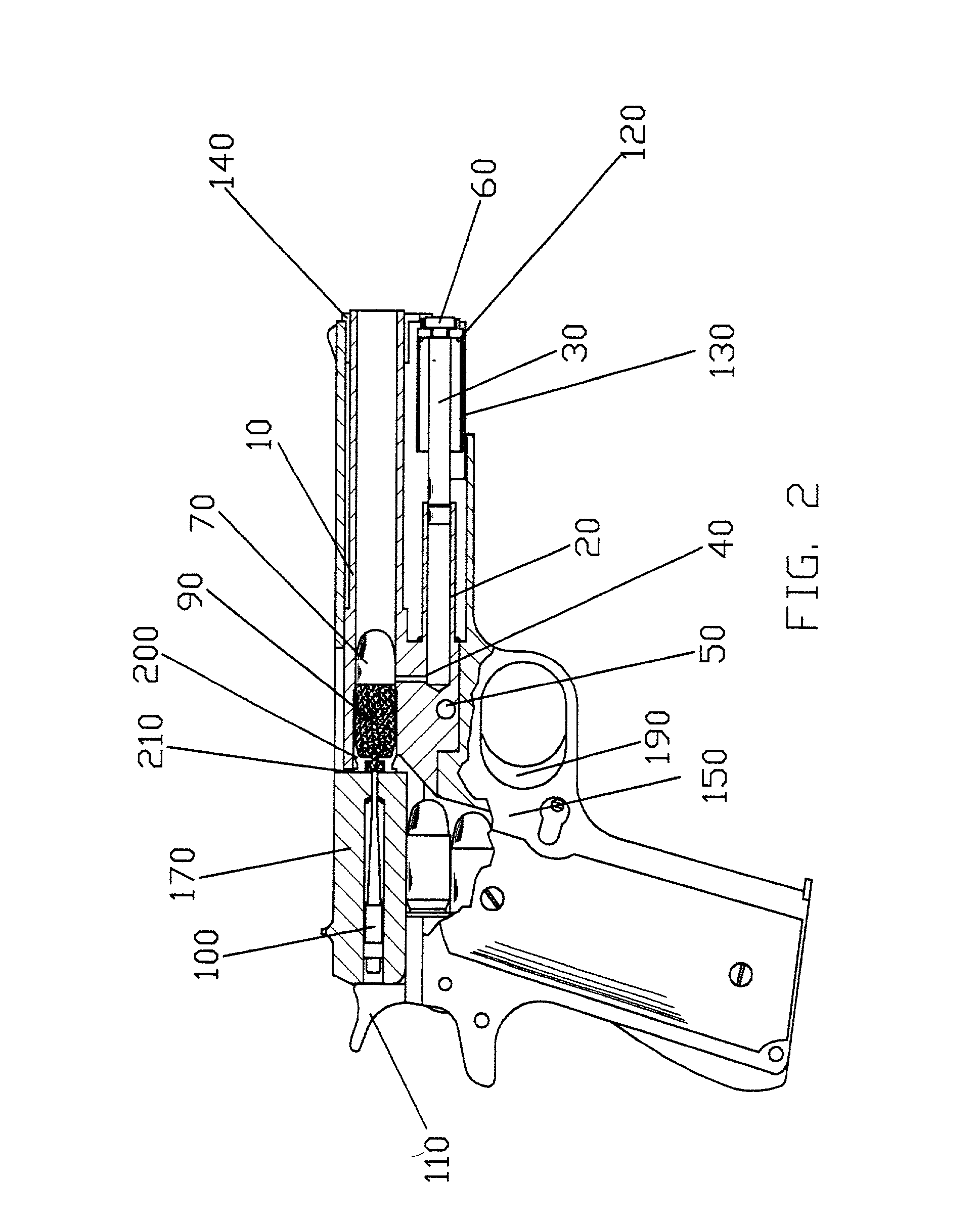
[0013] Referring to FIG. 1, the weapon provided with the gas retarded operating system-is ready to fire. The hammer 110 is cocked, being held by a sear, not shown. A cartridge case 200 with propellant 80 and projectile 70 is loaded into the chamber of barrel 10. Slide 170 is in its forward position with the barrel bushing 140 centering the muzzle of barrel 10. Barrel 10 is retained to frame 150 by pin 50. Gas cylinder 20 is part of barrel 10. The rear of gas piston 30 is centered in the front of gas cylinder 20. The front of gas piston 30 is located in recoil spring plug 130 by centering screw 60. (More detail of centering screw 60 is shown in FIG. 6) The rear of recoil spring 120 fits around gas cylinder 20 and rests against the lower portion of barrel 10. The front of recoil spring 120 rests against the inside of recoil spring plug 130. Recoil spring plug 130 is retained by barrel bushing 140. Barrel bushing 140 is secured to slide 170. Barrel bushing 140 has a sliding fit with ba...


PUM


Abstract

The closure of a blowback operated weapon is augmented by a gas cylinder and piston. The piston is self centering.

Description

BACKGROUND OF INVENTION[0001] Typical semiautomatic pistols are equipped with moveable barrels which are locked into moveable slides during firing. The required clearances between the interfacing moveable parts and the motion of the parts during firing contributes to reduction in accuracy of the weapon. The required number of parts and the inherently complex machining of the parts of conventional pistols contributes to high cost of finished weapons. The M1911 series of U.S. service pistols and other pistols based upon the Browning operating system is the most common high powered semiautomatic pistol design in the world. The relative motion of the barrel with the frame in these weapons requires careful gunsmithing in order for these pistols to shoot accurately.SUMMARY OF PRESENT INVENTION[0002] The present invention provides for more accurate fire and for lower cost manufacture for semiautomatic pistols and other short barreled weapons firing high powered cartridges. Unlike typical m...

Claims


Application Information

Patent Timeline
IPC IPC(8): F41A3/62
CPCF41A3/62
Inventor ADKINS, JOHN
Owner NETWORK CUSTOM GUNS
Why Eureka
Try Eureka