
Portable batting practise cage and method of using the same

a batting cage and portable technology, applied in the field of portable batting cages, can solve problems such as practical considerations, and achieve the effect of reducing the likelihood

Inactive Publication Date: 2002-07-25
BRUYER ROBERT WILLIAM +1
View PDF0 Cites 28 Cited by
  • Summary
  • Abstract
  • Description
  • Claims
  • Application Information

AI Technical Summary

Benefits of technology

[0003] What is required is a portable batting cage that can be rapidly erected with a minimum of assembly.
[0007] Although beneficial results may be obtained through the use of the portable batting practise cage, as described above, even more beneficial results may be obtained through the addition of selected features and combinations of features, as will hereafter be further described. It is preferred that a domed shell be used. It is preferred that each of the several support poles be capable of bending to assume an arch configuration. It is preferred that foldable poles be used with a plurality of interlocking sections held together with a flexible line, such as are now becoming popular with tents. It is preferred that ends of each of the several transversely extending rows of externally positioned loops terminate in pole engaging members so that the poles can be slid through the loops and engaged with the pole engaging members to maintain them in an arch configuration. For reasons of safety, it is preferred that a closure be provided for blocking off a portion of the pitching port and reducing the likelihood of the batter driving a ball back through the pitching port.

Problems solved by technology

The only limitations are practical considerations.

Method used


Image

  • Portable batting practise cage and method of using the same
  • Portable batting practise cage and method of using the same
  • Portable batting practise cage and method of using the same

Examples


Embodiment Construction

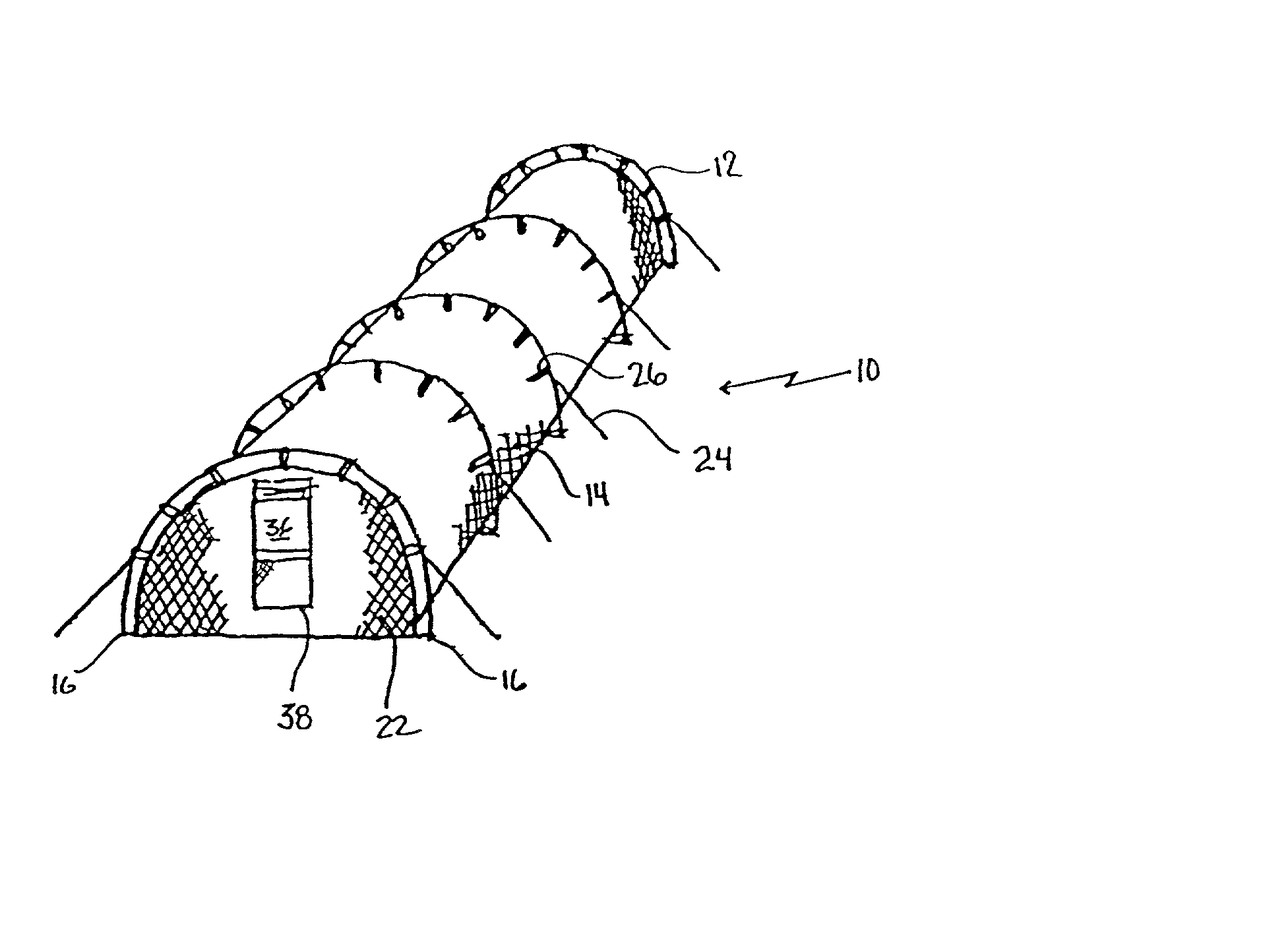
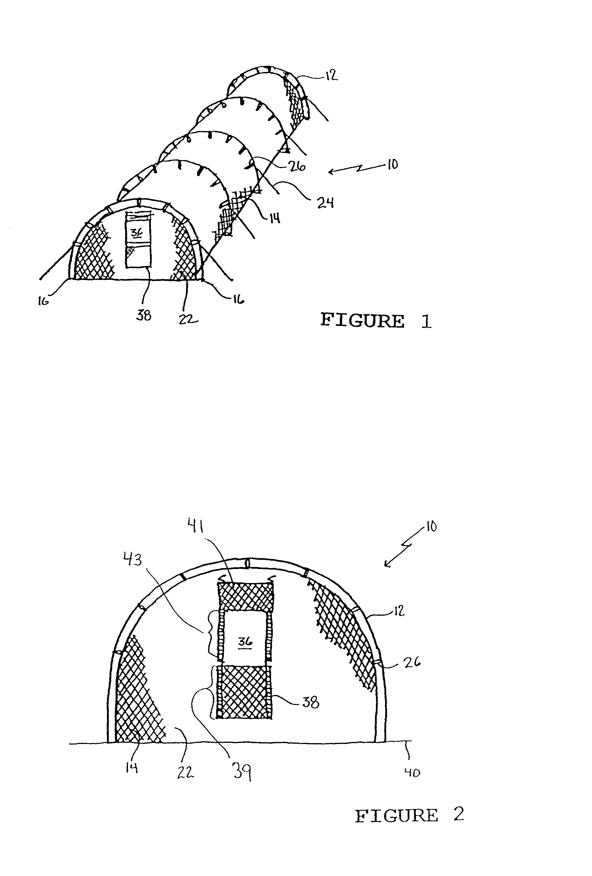
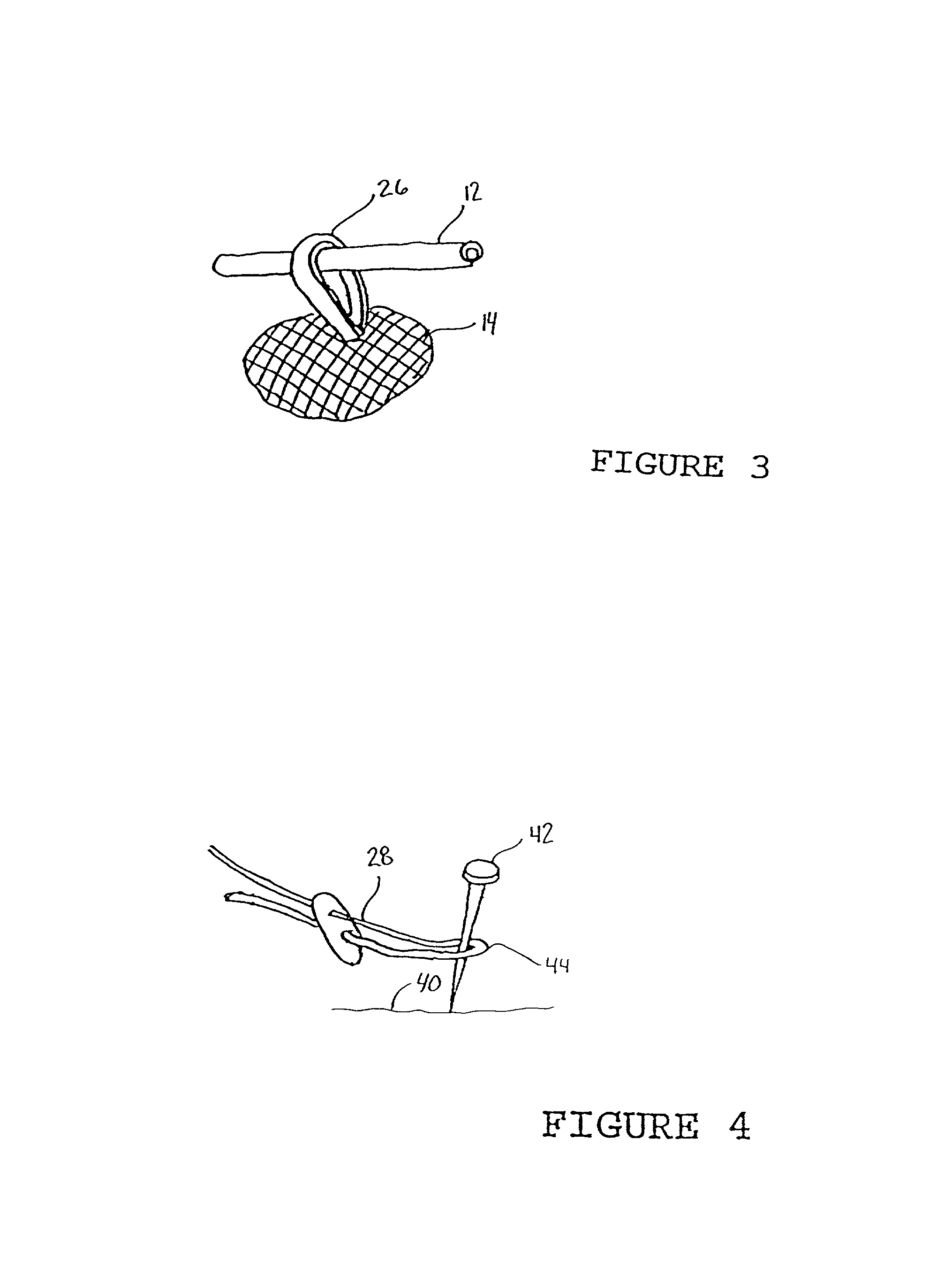
[0016] The preferred embodiment, a portable batting practise cage generally identified by reference numeral 10, will now be described with reference to FIGS. 1 through 7.

[0017] Structure and Relationship of Parts

[0018] Referring to FIG. 1, there is provided a portable batting practise cage 10 which includes several flexible support poles 12 and a non-supporting mesh dome shell 14. Support poles 12 have opposed ends 16 and are capable of bending to assume an arch configuration. Referring to FIG. 7, support poles 12 consist of a plurality of interlocking sections 18 held together with a flexible line 20 that enables support poles 12 to be folded for storage.

[0019] Referring to FIG. 6, dome shell 14 has a substantially planar end wall 22, depending anchor lines 24 and several transversely extending rows of externally positioned loops 26. In the illustrated embodiment, dome shell 14 is depicted as having upper anchor lines 28 or lower anchor lines 30. Referring to FIG. 4, upper anchor l...


PUM


Abstract

A portable batting practise cage and method of use of the same. The portable batting practise cage includes several support poles and a non-supporting mesh shell. The shell has a substantially planar end wall, depending anchor lines and several transversely extending rows of externally positioned loops. The shell is supported and held erect by inserting one of the several support poles through each of the several transversely positioned rows of externally positioned loops, and anchoring the mesh shell to a ground surface by means of the anchor lines. A pitching port is provided through the planar end wall of the shell, enabling a pitcher positioned outside of the structure to pitch to a batter positioned within the mesh shell.

Description

FIELD OF THE INVENTION[0001] The present invention relates to a portable batting practise cage.BACKGROUND OF THE INVENTION[0002] Batting practise cages are used as a training tool by coaches of amateur baseball teams. The batting practise cages generally consist of a support frame with an exterior covering of mesh netting. An "L" shaped protective screen is provided within the batting practise cage for the coach to stand behind as he pitches the ball to the batters. There have been batting cages marketed as being "portable" but to date these portable batting cages still require a considerable amount of time for assembly.SUMMARY OF THE INVENTION[0003] What is required is a portable batting cage that can be rapidly erected with a minimum of assembly.[0004] According to one aspect of the present invention there is provided a portable batting practise cage which includes several support poles and a non-supporting mesh shell. The shell has a substantially planar end wall, depending ancho...

Claims


Application Information

Patent Timeline
Patent Type & Authority Applications(United States)
IPC IPC(8): A63B71/02
CPCA63B71/022
Inventor BRUYER, ROBERT WILLIAMLEGAULT, DENIS BERNARD
Owner BRUYER ROBERT WILLIAM
Learn More