Titania-based porous substance and catalyst

a porous substance and titania technology, applied in the field of titania-based porous substances and catalysts, can solve the problems of difficult to produce super fine particulate titania, high temperature, and high cost of catalysts, and achieve the effect of reducing the risk of agglomeration of catalytic ingredients at an elevated temperatur

Inactive Publication Date: 2002-08-08
TOYOTA CENT RES & DEV LAB INC
View PDF6 Cites 14 Cited by
  • Summary
  • Abstract
  • Description
  • Claims
  • Application Information

AI Technical Summary

Benefits of technology

[0023] Thus, in accordance with an aspect of the present invention, since the present titania-based porous substance exhibits the x-ray diffraction peak resulting from lattice planes whose spacing falls in a range of 0.290.+-.0.002 nm, it includes crystals other than the anatase phase crystal. Therefore, in the present titania-based porous substance, a large number of crystal planes exist so that a catalytic ingredient is loaded with a lowered rate within the identical crystal plane. Hence, the catalytic ingredient is inhibited from agglomerating. As a result, the present catalyst is kept from exhibiting degraded activities even after it is subjected to a durability test.
[0024] Moreover, since the present titania-based porous substance has a median pore diameter which falls in the meso-pore range and exhibits a sharp pore diameter distribution, molecules can interact with each other highly frequently therein. Accordingly, the present titania-based porous substance is extremely useful as a reaction field to which molecules contribute. Therefore, in accordance with an aspect of the present invention, the present catalyst is good in terms of the H.sub.2O adsorption ability. At the same time, since there exists CO which is weakly adsorbed onto the catalytic ingredient, the present catalyst exhibits a high CO shift reactivity from a low temperature region.

Problems solved by technology

However, by the conventional production processes which are carried out in a liquid phase, the resulting titania particles agglomerate, and the particles also grow when they are calcined at a high temperature.
Accordingly, it has been difficult to produce super fine particulate titania.
Therefore, since the catalytic ingredient is loaded within the identical crystal plane with a higher rate, there arises a problem in that the catalytic ingredient is likely to agglomerate at an elevated temperature.
While, in the CO shift reaction catalyst, which is used in a fuel reforming system of an internally reforming type fuel cell being boarded in a mobile body, such as an automobile, or which is used in an exhaust gas purifying system for reforming CO, contained in an automotive exhaust gas, into H.sub.2, and reducing NO.sub.x, being stored on the catalyst, by using the resulting H.sub.2, the catalyst is required to exhibit a high activity under the reaction condition of a large space velocity, because the catalytic reactor is limited in terms of the size.
However,the conventional Cu--Zn-based catalysts suffer from a drawback in that they exhibit a low activity under the reaction condition of a large space velocity.
Accordingly, under the reaction condition of a large space velocity, for example, in a fuel reforming system of an internally reforming type fuel cell or in an automotive exhaust gas purifying system, it is difficult for the conventional Cu--Zn-based catalysts to efficiently convert CO into H.sub.2.
Accordingly, it is disadvantageous for the conversion from CO to H.sub.2.
Therefore, even when the reaction temperature is heightened in order to compensate for the lowered activity under the condition of a large space velocity, it is difficult for the conventional Cu--Zn-based catalysts to efficiently convert CO into H.sub.2.
Furthermore, when the conventional CO shift reaction catalysts are used in a fuel reforming system of an internally reforming type fuel cell or in an automotive exhaust gas purifying system, there arises a case where the reaction field is temporarily turned into a high temperature atmosphere under certain service conditions.
Hence, the conventional CO shift reaction catalysts suffer from the following problem.
Thus, it is more difficult for the conventional CO shift reaction catalyst to efficiently convert CO into H.sub.2.
Accordingly, there arises a problem in that such a system enlarges.
Moreover, in order to supply a water vapor, a large quantity of energy is required to evaporate water.
Consequently, the energy efficiency deteriorates in view of such a system as a whole.
As a result, there arises a drawback in that the activities of the catalyst lower sharply.
There arises a drawback in that the activities of the catalyst have been degraded sharply by the reduction of active sites.
When the loading amount is less than 0.05 parts by weight with respect thereto, the resulting catalyst might not fully reveal the advantage of igniting CO at a low temperature and the water-gas shift reactivity.
When the loading amount is more than 30 parts by weight with respect thereto, there might arise a case where the noble metal clogs the meso-pores, or the resulting catalyst might not fully reveal the advantage of inhibiting the noble metal from sintering.
Secondly, deposits of oxide precursors are precipitated from the raw material solution.
Thirdly, the resulting deposits are aged by holding them at a temperature of room temperature or more.
Thus, such heating is not preferable because the production cost goes up sharply.
When the calcining temperature is less than 300.degree. C., the resulting titania-based porous substance might virtually lack the stability when it is used as a support for catalysts.
When the calcining temperature is more than 900.degree. C., such calcining might result in lowering the specific surface area of the resulting titania-based porous substance.

Method used


Image

  • Titania-based porous substance and catalyst
  • Titania-based porous substance and catalyst
  • Titania-based porous substance and catalyst

Examples


example no.2

EXAMPLE NO. 2

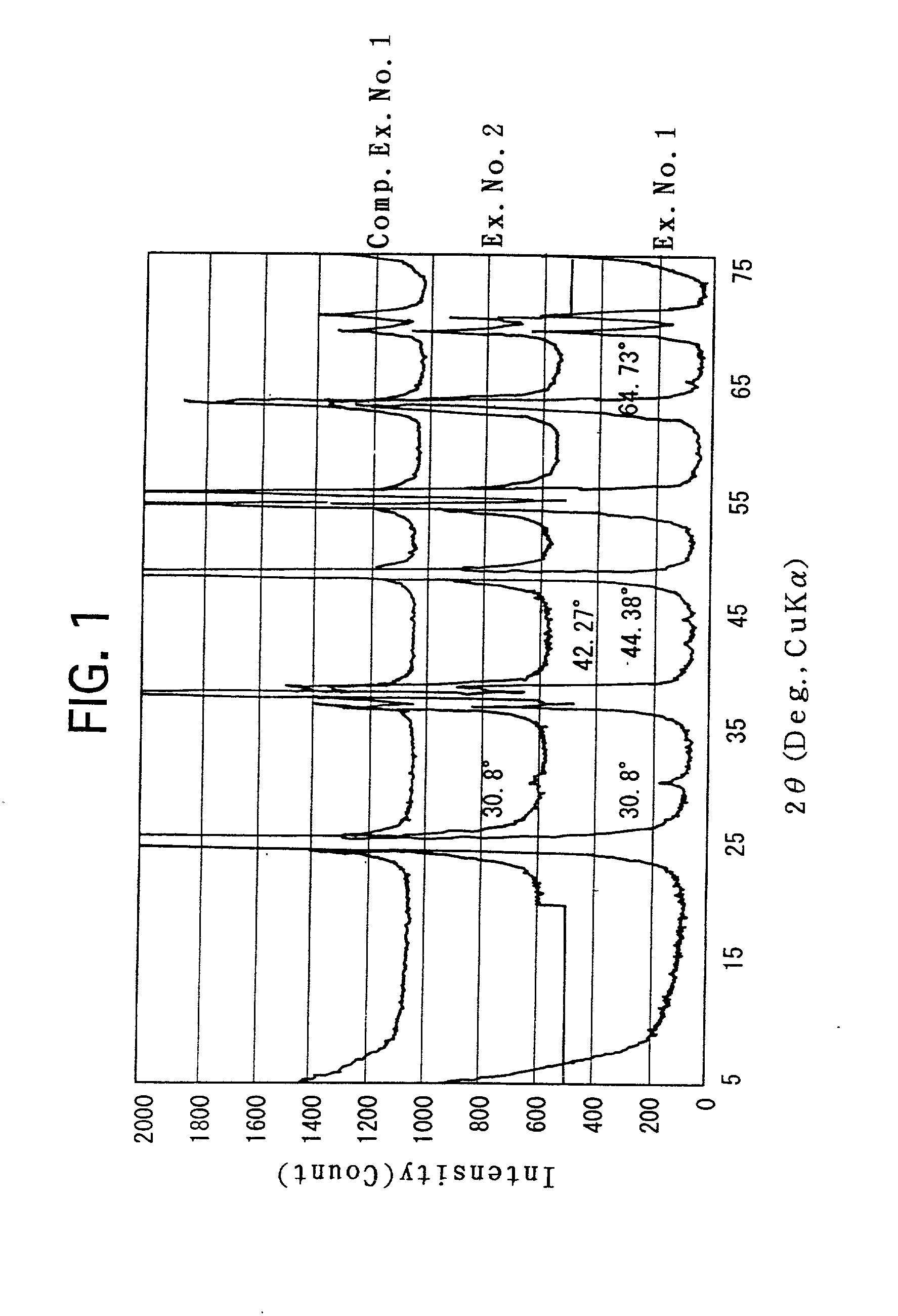
[0051] Deposits were precipitated in the same manner as Example No. 1. The aging step was similarly carried out. Thereafter, stirring and filtering were repeatedly carried out by using ion-exchange water to wash the deposits. The resulting deposits were dried, and were calcined in the same manner as Example No. 1. The resulting titania porous substance was subjected to the measurements, observation and analysis in the same manner as Example No. 1. The respective resulting values, etc., are set forth in Table 1 or illustrated in FIG. 1.

[0052] Note that, according to the result of the TEM observation, particles, which had an aspect ratio of 2.3 or less, were sparsely agglomerated to form the meso-pores in the titania porous substance of Example No. 2 as well.

example no.3

EXAMPLE NO. 3

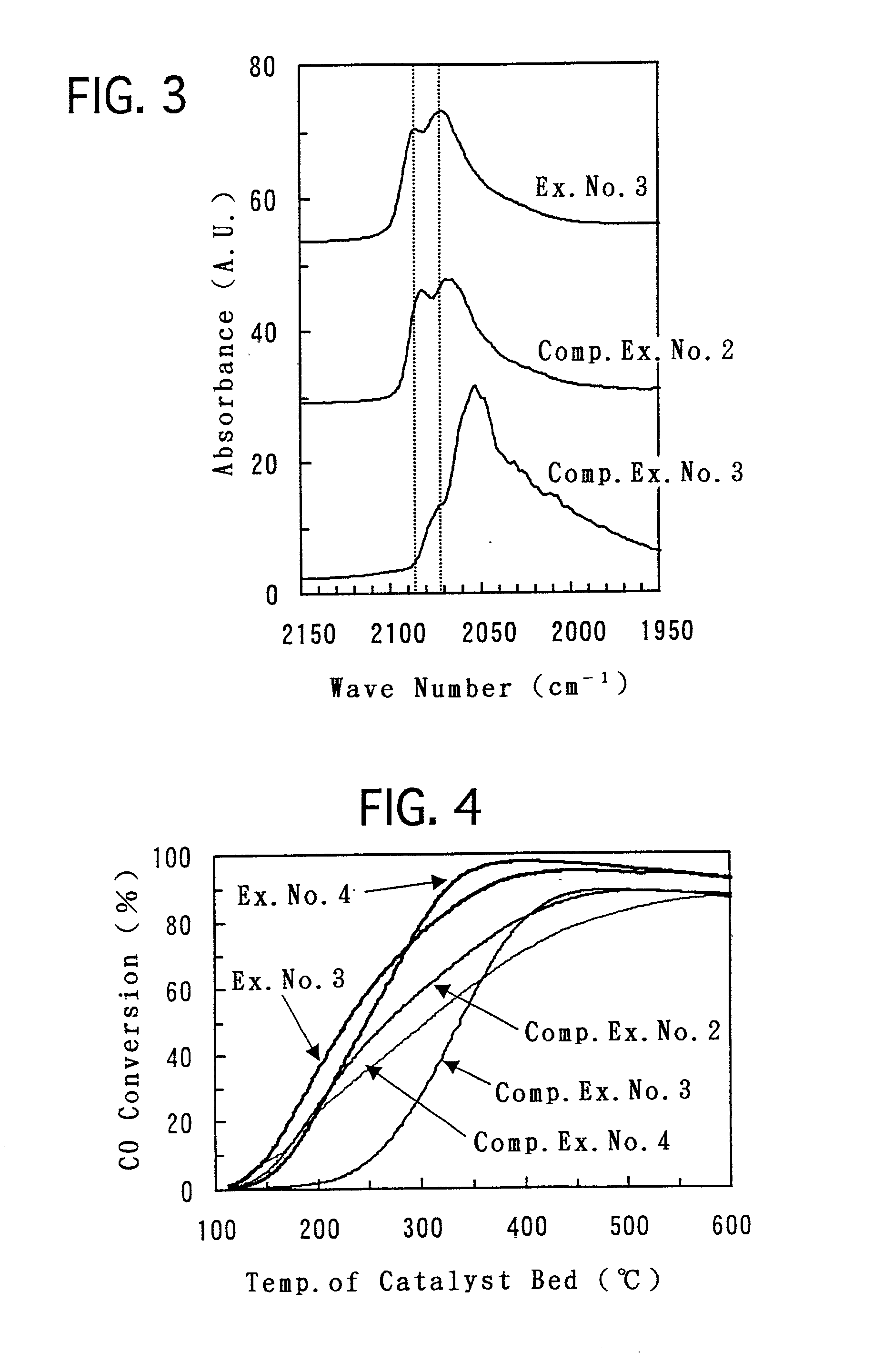
[0057] To a powder of the titania porous substance prepared in Example No. 1, Pt was loaded by impregnation by using a dinitrodiammine platinum nitrate aqueous solution so that the Pt was loaded in an amount of 1 g with respect to 100 g of the titania porous substance. Then, after drying the powder, the powder was calcined in air at 300.degree. C. for 3 hours. Finally, after compacting the powder, the resulting compacted substance was pulverized. Thus, a pelletized catalyst of Example No. 3 was prepared which had a particle diameter of from 0.5 to 1.0 mm.

example no.4

EXAMPLE NO. 4

[0058] Except that a powder of the titania porous substance prepared in Example No. 2 was used instead of the titania porous substance prepared in Example No. 1, a pelletized catalyst of Example No. 4 was prepared in the same manner as Example No. 3.


PUM

PropertyMeasurementUnit
pore diameteraaaaaaaaaa
diameteraaaaaaaaaa
diameteraaaaaaaaaa

Abstract

A titania-based porous substance includes titania as a principal ingredient, and exhibits an x-ray diffraction peak resulting from lattice planes whose spacing falls in a range of 0.290±0.002 nm. Thus, it includes crystals other than the anatase phase crystal. Therefore, a large number of crystal planes exist therein. As a result, when a catalytic ingredient is loaded on it, the catalytic ingredient is loaded with a lowered rate within the identical crystal plane.

Description

[0001] 2. Field of the Invention[0002] The present invention relates to a titania-based porous substance in which titania is a principal ingredient, and a catalyst in which the titania-based porous substance makes a support. The titania-based porous substance according to the present invention is extremely useful for a catalytic support, an adsorption agent, a filter, or the like. Moreover, the catalyst according to the present invention, for example, exhibits a high CO shift reactivity from a low temperature range, and can carry out removing CO and generating H.sub.2 with high efficiencies.[0003] 2. Description of the Related Art[0004] A titania powder has been utilized widely not only as pigments but also as a raw material for catalytic supports, deodorizing agents, electronic ceramics, and the like. As for the production process, the sulfur method and the chlorine method are the representative ones. In addition thereto, the chemical vapor-phase epitaxy method, etc., have been kno...

Claims


Application Information

Patent Timeline
Patent Type & Authority Applications(United States)
IPC IPC(8): B01J20/04B01D39/20B01J21/06B01J23/40B01J23/42B01J32/00C01B3/16C04B35/46
CPCB01J21/06B01J21/063B01J23/40B01J23/42C01B3/16Y02P20/52
Inventor YAMAZAKI, KIYOSHIHATANAKA, MIHOSUDA, AKIHIKOFUKUI, MASAYUKI
Owner TOYOTA CENT RES & DEV LAB INC
Why Eureka
Try Eureka