Method for data rate selection in a wireless communication system

a wireless communication system and data rate selection technology, applied in the field of wireless communication, can solve the problems of limited resources for the number of users that can be supported by a base station, waste of limited signaling channel bandwidth, and large number of bits to specify the data rate,

Inactive Publication Date: 2002-08-15
GEMPLU
View PDF16 Cites 94 Cited by
  • Summary
  • Abstract
  • Description
  • Claims
  • Application Information

AI Technical Summary

Problems solved by technology

In wireless communication systems such as Code Division Multiple Access (CDMA) systems the number of users that are supportable by a base station is limited by resources such as available transmit power and a number of orthogonal codes that are used to distinguish channels.
Using the large number of bits to specify the data rate is wasteful of limited signaling channel bandwidth.
Using carrier to interference ratios for base station selection during handoffs involving a data user may result in the user selecting a base station that does not provide the maximum overall data rate to that user.
Conversely, a rate determination algorithm that does not

Method used


Image

  • Method for data rate selection in a wireless communication system
  • Method for data rate selection in a wireless communication system
  • Method for data rate selection in a wireless communication system

Examples


case i

[0077] Case I

[0078] Two fingers assigned by the data mobile m to multipath rays from serving cell 1 to recover energy and one finger assigned to neighboring cell 2 to decode control information:

[0079] Ec / Nt (l,m,k) 2 Ec / Nt ( 1 , m , k ) = ( Eb / Nt ) PG = 1 d( k + d ) ( c 1 / ( c 1 + c 2 ) ) { [ 1( I 0 / E c1 sum ) -1 d( k ) - ( 1 d( k ) +1 vo( k )) ( 1 - c 1 ) ( c 1 + c 2 ) ] (c 2 d( k + d ) +2 vo( k + d )) ( 2 d( k ) +2 vo ( k )) + ( 1 - c 1 )( c 1 + c 2 )( 1 d ( k ) +1 vo( k )) } + = 1 d( k + d ) ( c 2 / ( c 1 + c 2 ) ) { [ 1( Io / E cl sum ) -1 d( k ) - ( 1 d( k ) +1 vo( k )) ( 1 - c 2 ) ( c 1 + c 2 ) ] ( 2 d( k + d ) +2 vo( k + d )) ( 2 d ( k ) +2 vo( k )) + ( 1 - c 2 )( c 1 + c 2 )( 1 d( k ) +1 vo( k )) } EQUATION A1

[0080] where:

[0081] k is the instant of measurement, i.e when the reverse feedback rate per code and antenna information (RAI) is computed

[0082] k+d is the instant of prediction, i.e. time of data reception; d is approximately three slots (3.75 ms).

[0083] d.sub.j...

case ii

[0094] Case II

[0095] One finger assigned to a ray from serving cell 1 to recover energy and two fingers assigned to neighboring cells 2 and 3 respectively to decode control information. 3 Ec / Nt ( 1 , m , k ) = ( Eb / Nt ) PG = 1 d( k + d ) { [ 1( Io / E cl sum ) -1 d( k ) - ( 1 d( k ) +1 vo( k )) ( 1 - c 1 ) c 1 ] [ (c 2 d( k + d ) +2 vo( k + d )) ( 2 d( k ) +2 vo( k )) 2 (2 + 3 )+(c 3 d( k + d ) +3 vo( k + d )) 3 ( 3 d( k ) +3 vo( k ))(2 + 3 ) ] + ( 1 - c 1 )c 1( 1 d( k ) +1 vo( k ))} EQUATION A2

[0096] where, in addition:

[0097] .beta.j is the ratio of path losses to the mobile of neighbor cell j to serving cell 1. This is estimated as the ratio of the pilot energy of cell j to that of cell 1 assuming equal pilot power fractions.

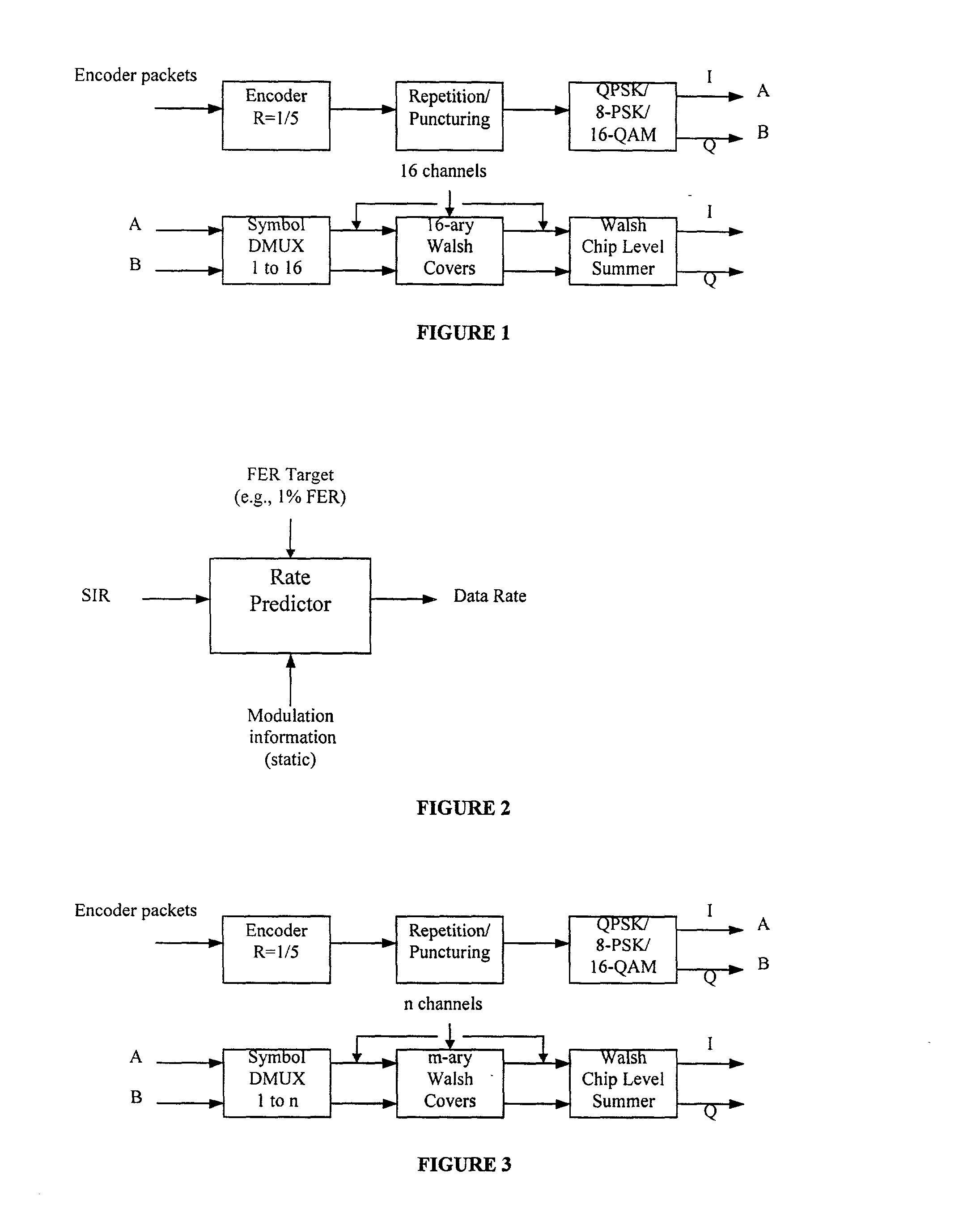
[0098] The Ec / Nt in the above expression is divided by M where M is the number of W-ary (e.g. W=16) Walsh codes available in D2. This yields the desired C / I per code for the cell 1.


PUM


Abstract

Data rate determination is provided in a system where the available power fraction and available Walsh codes in each active leg are dynamically changing over time. This method adapts the rate (modulation and coding) based on the combined resource (power & code space) levels seen at each cell. The method results in maximization of the rate supportable by each cell given their resource constrained situation while meeting the constraints of target packet or frame error rate and orthogonality. Furthermore, improved fast cell selection by the mobile results due to this approach that is based on knowledge of combined resource (power & code space) levels across the cells in the active set.

Description

[0001] 1. Field of the Invention[0002] The present invention relates to communications; more specifically, wireless communications.[0003] 2. Description of the Related Art[0004] In wireless communication systems such as Code Division Multiple Access (CDMA) systems the number of users that are supportable by a base station is limited by resources such as available transmit power and a number of orthogonal codes that are used to distinguish channels. In many CDMA systems the orthogonal codes are derived from a set of 16 orthogonal Walsh codes.[0005] In CDMA systems that support both voice and data communications the power and code resources are shared between the voice and data users. Typically, each voice user is provided with one orthogonal code and sufficient transmit power to maintain an acceptable signal to noise ratio or frame error rate. The remaining transmit power and orthogonal codes are provided to one data user at a time on a time shared basis. As a result, for a short per...

Claims


Application Information

Patent Timeline
IPC IPC(8): H04J11/00H04J13/00H04L1/00
CPCH04B2201/70703H04J13/0048H04L1/0003H04L1/0009H04L1/0022H04L1/0025H04W28/22H04W72/042H04W72/0466H04W72/23
Inventor GOPALAKRISHNAN, NANDUKADABA, SRINIVAS R.KHAN, FAROOQ ULLAHNANDA, SANJIVSUNAY, MEHMET OGUZSUNDARAM, GANAPATHY SUBRAMANIAN
Owner GEMPLU
Why Eureka
Try Eureka