Spectral filtration of optical radiation

Inactive Publication Date: 2002-09-12
STRATEGIC LIGHT
View PDF0 Cites 10 Cited by
  • Summary
  • Abstract
  • Description
  • Claims
  • Application Information

AI Technical Summary

Benefits of technology

0018] In contrast to the known filters, in the present invention diffraction of the filtered light and electrically controlled phase matching take place in separate layers. Holographic gratings are recorded in the photosensitive material which may have poor electrooptical properties, and therefore there is a possibility to select the materials wi

Problems solved by technology

The light reflected on other gratings operating for different wavelengths is subjected to a destructive in

Method used


Image

  • Spectral filtration of optical radiation
  • Spectral filtration of optical radiation
  • Spectral filtration of optical radiation

Examples


Example

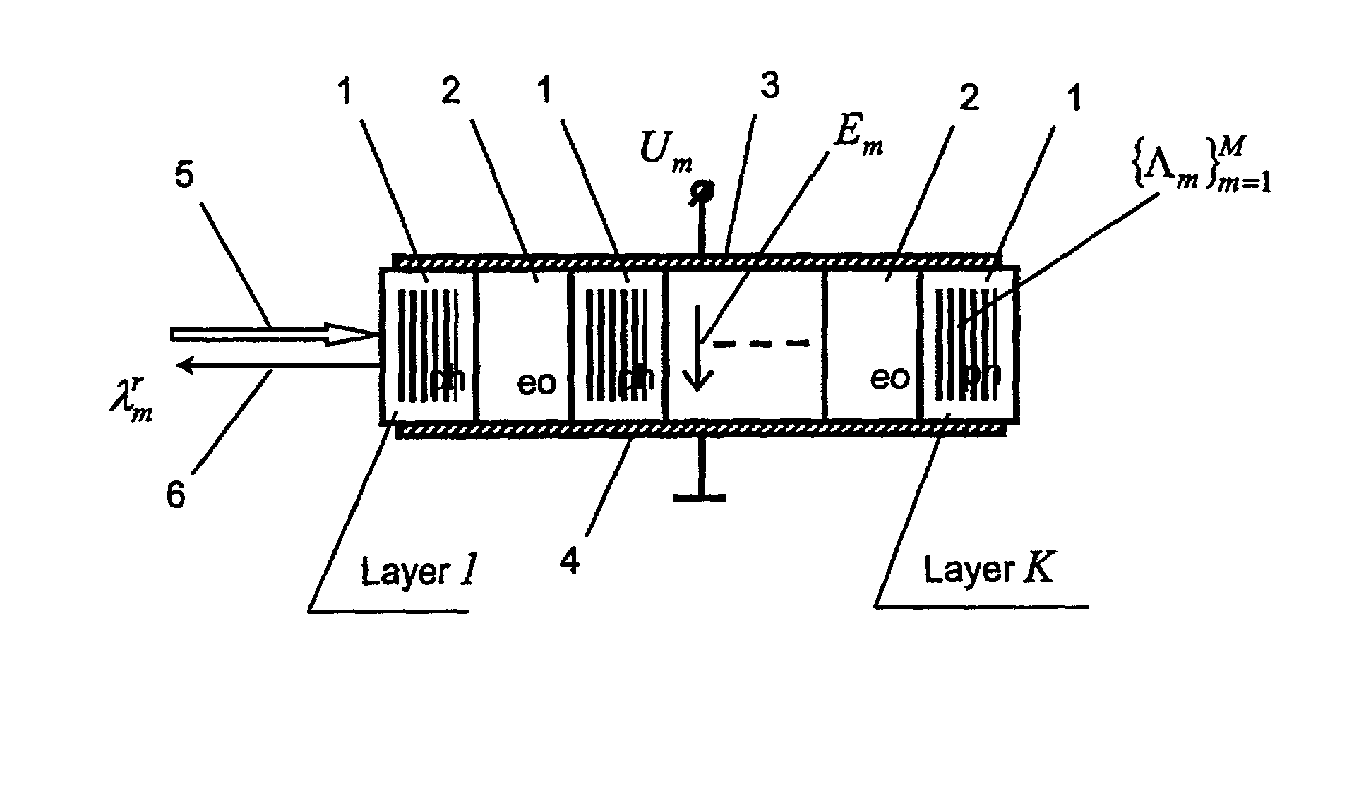
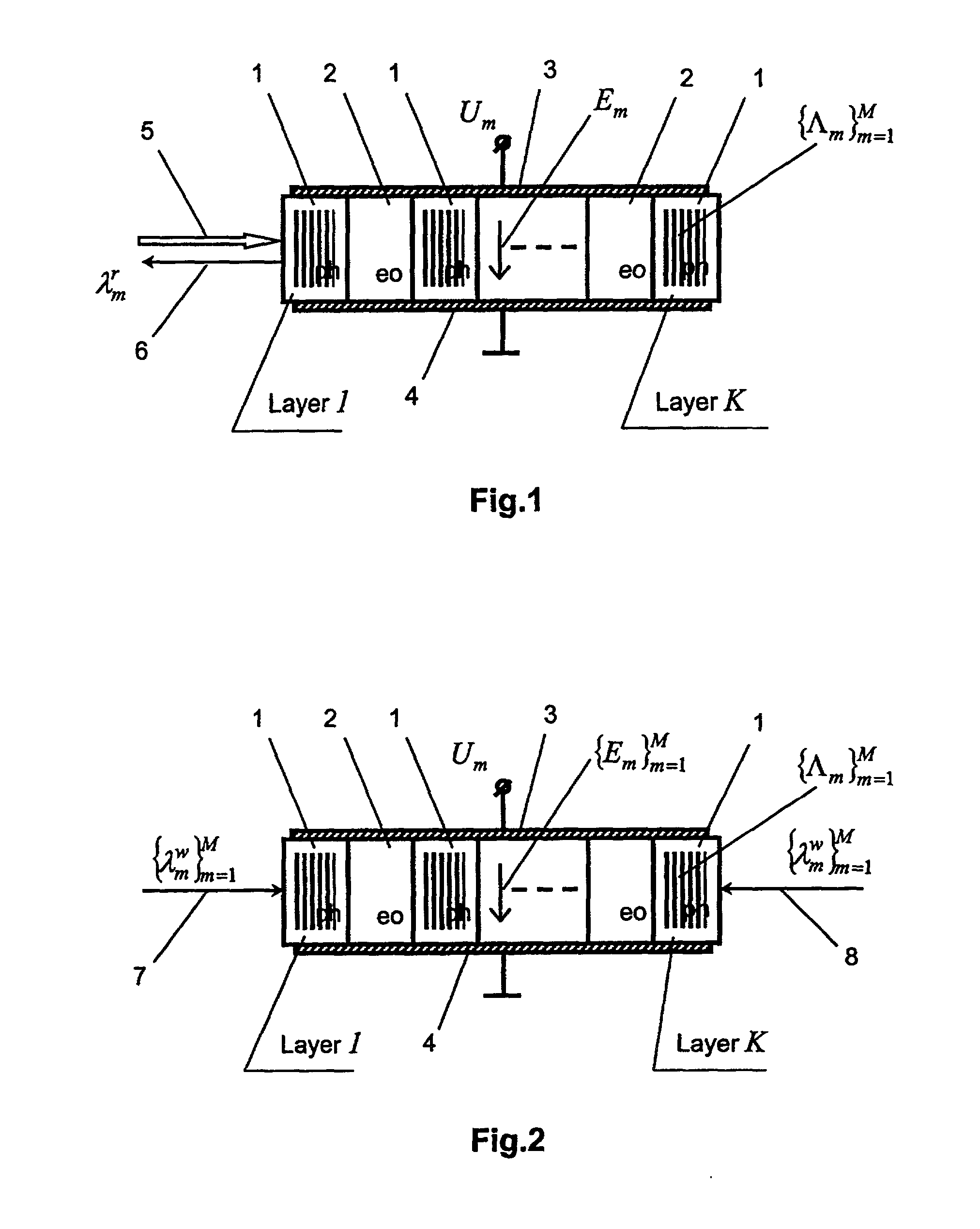
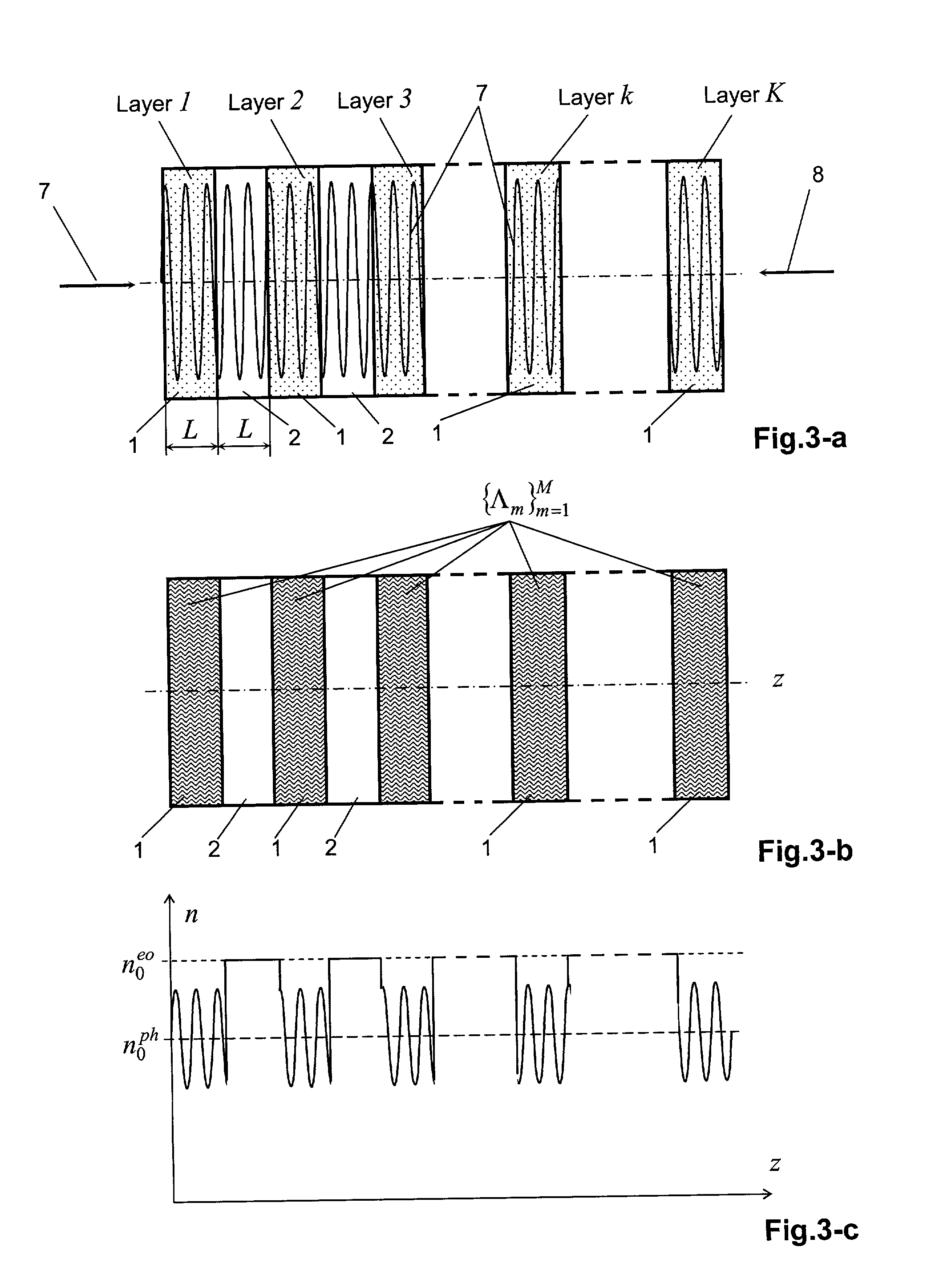
[0026] The filter of the present invention shown in FIG. 1 comprises layers 1 of a photosensitive material (ph) used to record volume phase holographic gratings and layers 2 of an electrooptic material (eo) whose index of refraction can vary depending on the strength of the applied external electric field. All the layers 1 and 2 form a multilayered structure with an optical contact between the layers, the layers 2 of the electrooptic material being interposed between the layers 1 of the photosensitive material, the total number of the photosensitive material layers being K. The total amount of gratings recorded in the filter is M, M.ltoreq.K. The m-th holographic grating has period .LAMBDA..sub.m, where m is the number of the grating. In each layer 1 of the photosensitive material the parts of all the gratings are recorded. The m-th holographic grating is recorded in the presence of a specified electric field E.sub.m, which is produced in the layers 2 of the electrooptic material wi...


PUM


Abstract

The present invention provides a new method for spectral filtering of optical radiation wherein the light to be filtered is directed onto two or more spaced apart layers of photosensitive material. A holographic grating is recorded in the layers so that each layer of the photosensitive material contains a portion of the recorded holographic grating. The output optical signal is formed as the result of interference of the light reflected due to the Bragg diffraction from the parts of the diffraction grating recorded in different layers. The reflected light propagates through the spaced apart electrooptical layers sandwiched between the photosensitive layers. The refractive index of the electrooptical layers is varied by the application of the appropriate electrical field to provide the phase difference between the reflected optical signals in order to obtain the desired value of the total output signal resulted from the interference of the reflected light.

Description

[0001] This application claims priority from an earlier filed U.S. Provisional patent application Serial No. 60 / 260,555, filed on Jan. 9, 2001, which application is incorporated by reference herein.FIELD OF THE INVENTION[0002] The present invention relates to an optical method and device for spectral filtering of optical radiation. More particularly, the invention relates to tunable optical narrow-band filters.BACKGROUND OF THE INVENTION[0003] Photorefractive crystals are considered to be very advantageous for development of narrow-band optical spectral filters which are based on electrically controllable holographic diffraction gratings recorded inside the crystals. Typical examples of such filters, employing photorefractive crystals, were described in the paper <<Volume holographic narrow-band optical filter", Optics Letters, Vol.18, No.6, pp.459-461 (1993); U.S. Pat. No. 5,684,611 "Photorefractive systems and methods"; and is U.S. Pat. No. 5,796,096 "Fabrication and applica...

Claims


Application Information

Patent Timeline
IPC IPC(8): G02F1/03
CPCG02F1/0311G02F1/0338G02F2201/305G02F2201/307G02F2203/055
Inventor PETROV, MICHAEL P.SHAMRAI, ALEXANDER V.PETROV, VICTOR M.
Owner STRATEGIC LIGHT
Why Eureka
Try Eureka