[0004] The invention is based on the object of providing a method of the kind mentioned above which allows an adequate and, in particular, damage-free thorough mixture also of temperature-sensitive plastic melts and compensates for the differences in temperature in melt flows coming from the extruder, so that the extrusion die can be provided with a homogeneous melt. The prerequisite is thus given to substantially reduce deviations in the wall thickness in new extrusion dies and to considerably reduce the configuration efforts for the dies, as well as to reduce the sensitivity towards different extruders and to even make the same frequently negligible in practical operation, thus enabling the application of dies even on different extrusion lines, which simplifies logistics and enables the optimization of the capacity utilization capabilities of the extrusion lines. Furthermore, a mixer is to be provided which allows a simple and appropriate performance of the method.
[0005] This object is achieved by the invention in such a way that the melt flow is divided into partial flows, which partial flows are twisted independent from one another about axes which extend in the direction of flow and are thereafter joined again into a common melt flow. As a result of the division of the melt flow into individual partial flows which are inherently turned and thereafter joined again, zones of the melt will come into contact with one another after the thorough mixture which were spaced from one another prior to the mixture. As a result of the now
close contact and short distances, any existing differences in temperature can level out relatively quickly. Stagnation zones are prevented in this process and a
mixing effect is obtained particularly in the radial direction, thus avoiding any danger of damage to any thermally unstable melts by longer dwell times of individual masses and thus preparing a substantially evenly tempered, homogeneous melt flow.
[0006] Particularly favorable mixing effects can be achieved when the partial flows are twisted about a rotational angle .alpha. which lies between approx. 90.degree. and 180.degree., with the direction of rotation being alternatingly either in the same or opposite direction, and when the melt flow is divided into four to twelve partial flows. As a result of the chosen number of partial flows there are sufficient contact zones and the spatial changes to the parts of the melt occur over respectively wide distances. Moreover, the partial cross sections remain large enough to keep the need for pressure low during the cross-flow, so that it is also possible to perform the thorough mixture in two or more successive steps. It is understood that this mixing process can also be combined with other known methods in order to homogenize the reunited melt flow over the flow cross section and to wipe out the traces of the partial flows, for which purpose a
mixing effect in the circumferential direction is particularly important.
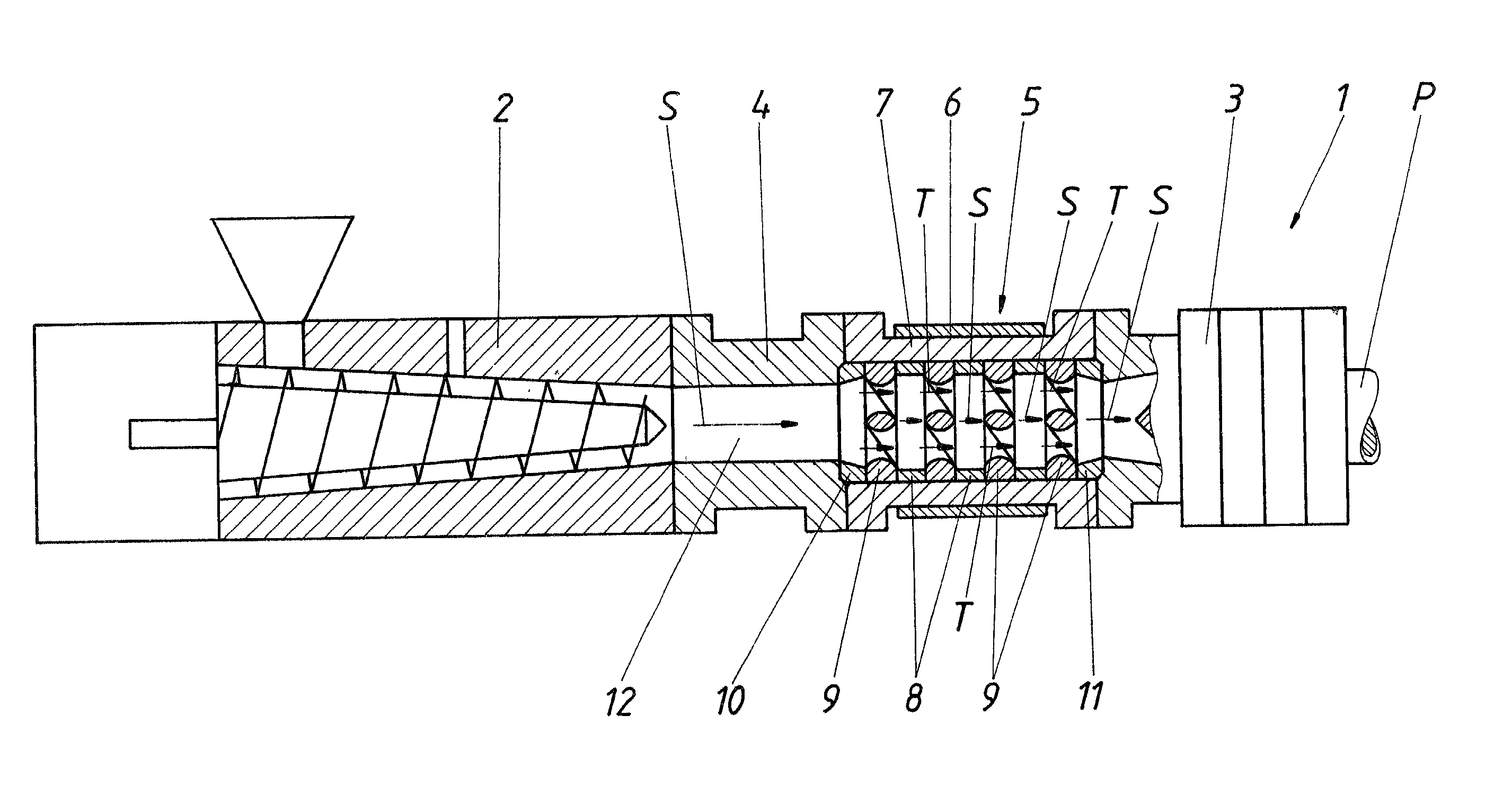
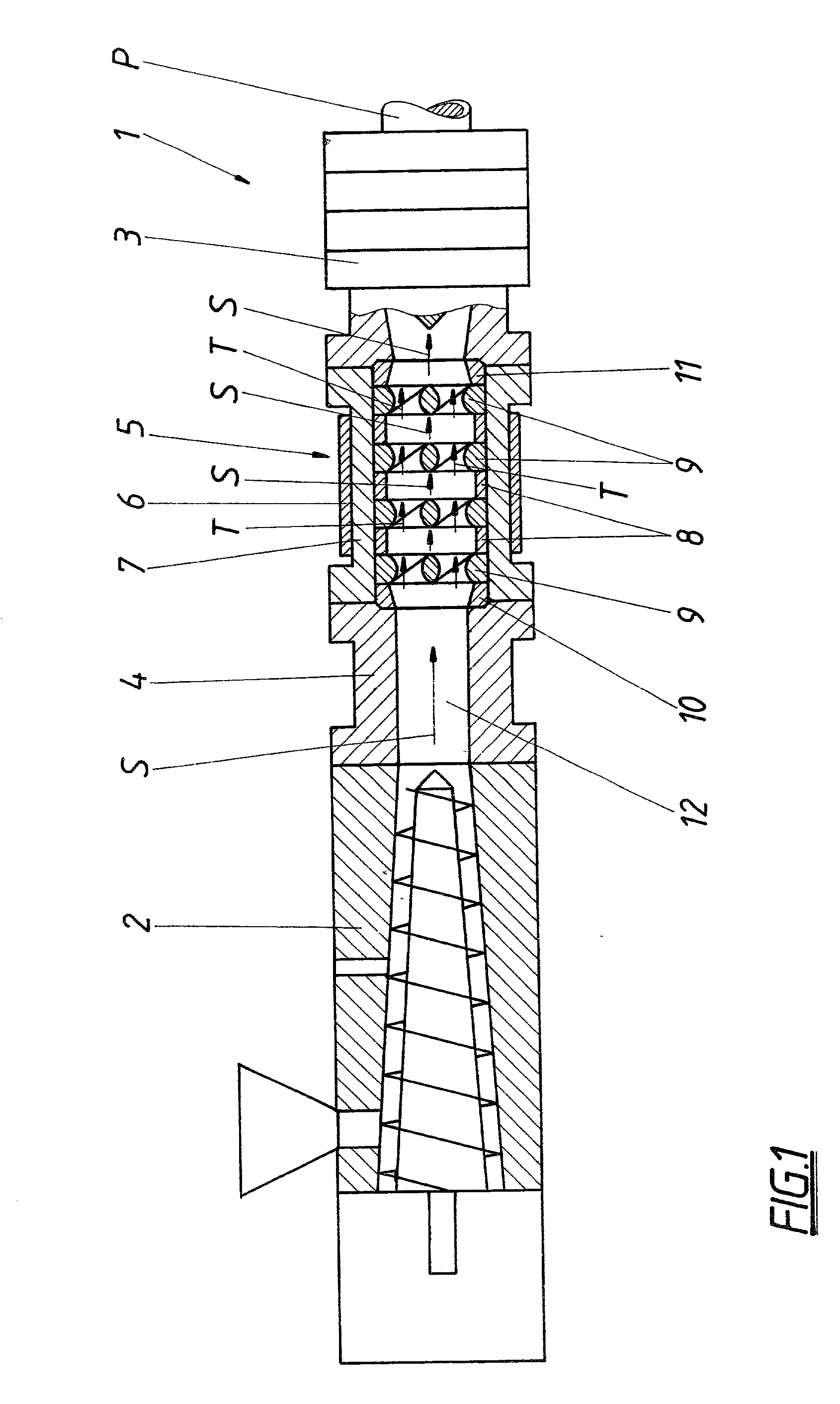
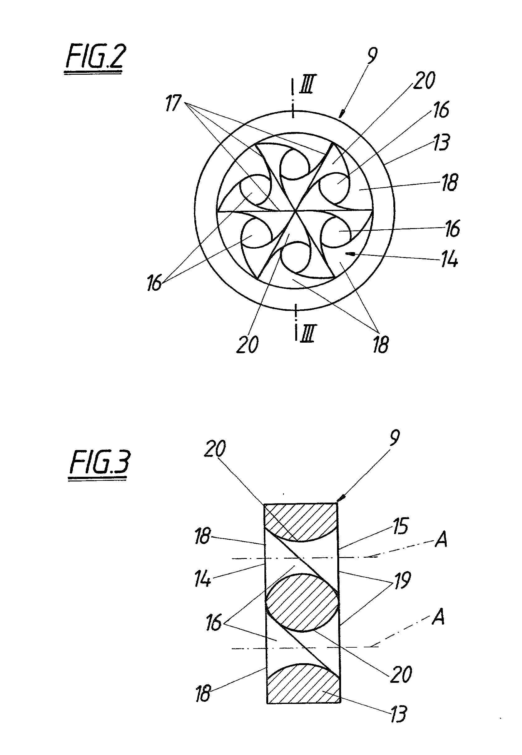
[0007] In order to perform the mixing process a mixer with a mixing body which can be integrated in the flow channel is proposed, with the mixing body comprising mixing channels with a twisting device, which channels extend from an inlet to an outlet. Said mixer allows with its mixing channels the perfect division of the melt flow into a respective number of partial flows and the twisting device ensures the desired twisting of the partial flows within the mixing channels, thus conveying melt particles from the central zone outwardly and outer particles in the opposite direction into the central zone, thus producing the desired radial mixing effect.
[0010] Appropriately, the inlet and outlet are subdivided by radial walls into several inlet and outlet openings, which inlet and outlet openings assigned in pairs to one another are mutually connected by the mixing channels. The inlet and outlet openings are only delimited by the inlet and outlet edges and are situated next to one another, so that the division or unification of the melt flow in the inlet and outlet zone can occur without any congestion or stagnation zones.
[0012] The mixing channels with the substantially polygonal cross sections which twist in the longitudinal direction of the channel can be flowed through by the partial streams without any major need for pressure, so that for increasing the mixing effect it is also possible to successively position two or several mixing bodies which are angularly offset about the direction of flow. Experiments with four successively disposed mixing bodies having shown very favorable mixing results. The angular offset of the mixing bodies ensures a respective enhancement of the mixing effect and prevents any mere increase of the twisting angle of the partial flows.

