Seismic receiver motion compensation

a receiver motion and seismic receiver technology, applied in seismology for waterlogging, instruments, reradiation, etc., can solve the problems of receiver motion and distortion of recorded seismic data, and cannot be neglected

Inactive Publication Date: 2002-09-12
WESTERNGECO LLC
View PDF0 Cites 22 Cited by
  • Summary
  • Abstract
  • Description
  • Claims
  • Application Information

AI Technical Summary

Problems solved by technology

This produces a distortion in the recorded seismic data.
However, it is now realized that the effects of receiver motion cannot be neglected.

Method used


Image

  • Seismic receiver motion compensation
  • Seismic receiver motion compensation
  • Seismic receiver motion compensation

Examples


Embodiment Construction

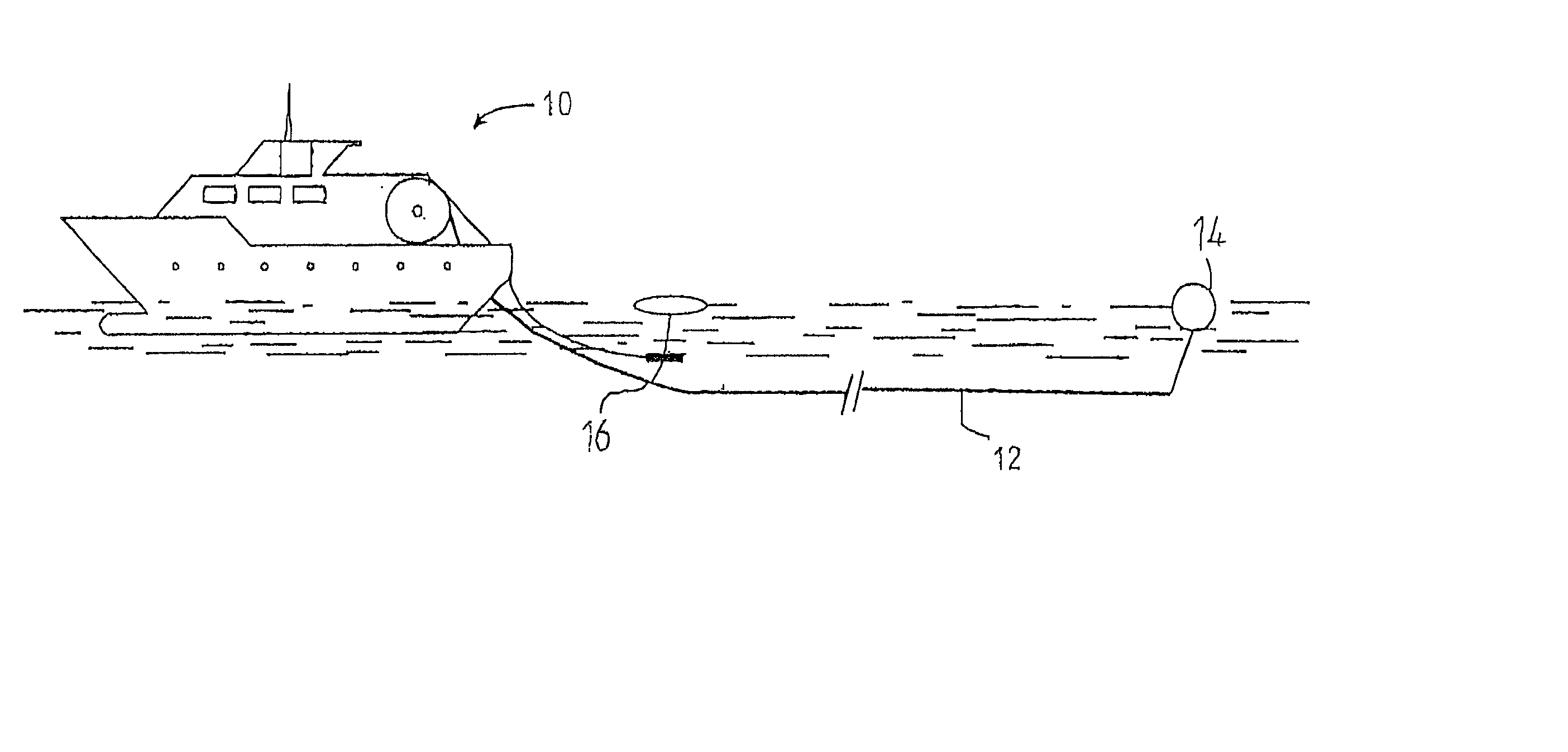
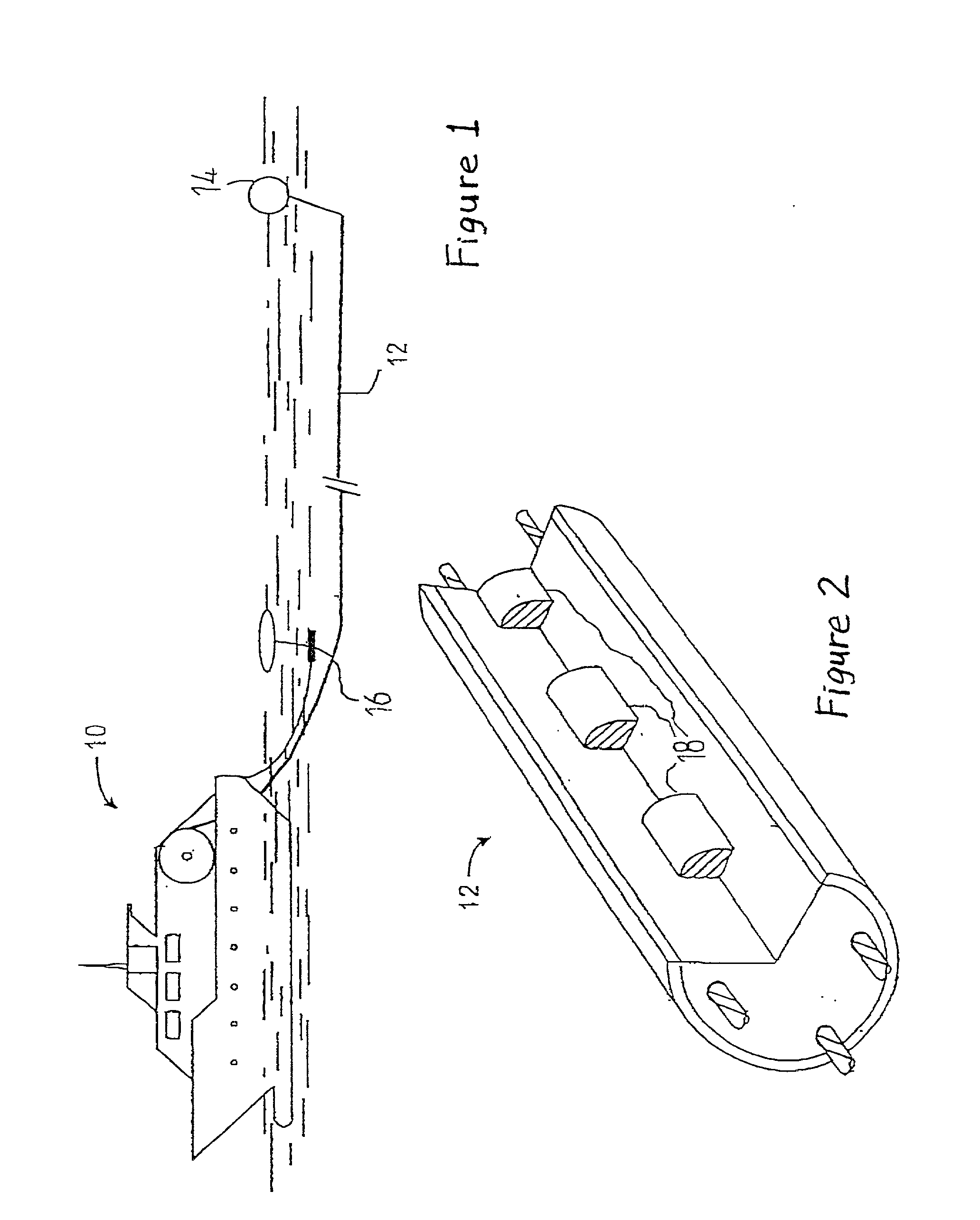
[0026] FIGS. 1 and 2 illustrate a typical setup for conducting a seismic survey at sea. An impulsive air gun source 16 is towed behind a seismic vessel 10 to produce acoustic energy pulses that travel through the sea and into the subsea formations before being reflected by sediment layers beneath the sea floor. Receivers 18 called hydrophones are also towed behind vessel 10 in a seismic streamer cable 12 for acquiring the reflected energy waves.

[0027] The hydrophones are interconnected by a transmission line (not shown) to a remote recording device located aboard the seismic vessel (also referred to herein simply as a "boat"). In this embodiment, adjacent hydrophones are not wired so as to form groups that generate a single output. Instead, the seismic data acquired by each of the hydrophones 18 are individually digitized and available for subsequent processing, preferably according to a proprietary process owned by the present Applicant and identified as "Q-Marine." These hydrophon...


PUM


Abstract

A method of compensating for seismic receiver motion in a marine seismic survey wherein at least one receiver is towed behind a moving seismic vessel comprises producing an acoustic energy wave at a seismic source, and recording the reflection arrival time t.sub.2 of the acoustic energy wave at the one receiver. The offset x between the source and the one receiver is determined. The normal moveout velocity V for the acoustic energy, and the velocity V.sub.B of the seismic vessel, are also estimated. A corrected reflection arrival time t.sub.1 of the acoustic energy wave is then determined by applying a time correction to the recorded reflection arrival time t.sub.2. The time correction is a function of the offset x, the normal moveout velocity V, and the velocity V.sub.B of the seismic vessel. The method is applicable to a plurality of receivers, whether the receivers are arranged in a single sensor acquisition system or hardwired to form receiver groups.

Description

BACKGROUND OF THE INVENTION[0001] 1. Field of the Invention[0002] This invention relates generally to marine seismic data acquisition, and more particularly to the compensation of seismic receiver motion during such data acquisition.[0003] 2. Description of the Related Art[0004] Seismic surveying is utilized to define subsurface geology and thereby improve the likelihood of successfully drilling into a subsurface formation that contains recoverable hydrocarbons. Surveys may be taken over land or sea, and typically involve the generation of a seismic wave via an explosion, impact, or vibration triggered at the surface by a seismic source. The structure of a subsurface formation is mapped by measuring the times required for the seismic wave to return to a plurality of receivers at the surface after having been reflected from interfaces between various subsurface formations, also known as sediment layers, having different physical properties. Variations in the reflection times from one...

Claims


Application Information

Patent Timeline
Patent Type & Authority Applications(United States)
IPC IPC(8): G01V1/36G01V1/00G01V1/38
CPCG01V1/362G01V1/3808G01V2210/532G01V2210/52
Inventor DOUMA, JANDRAGOSET, WILLIAM H.
Owner WESTERNGECO LLC
Why Eureka
Try Eureka