

Radio LAN master station system
a master station and radio lan technology, applied in the field of local area network radio lan master station system, can solve the problems of high interference rate, poor communication quality, and inability to use such frequency band systems, and achieve the effect of long distance communication
- Summary
- Abstract
- Description
- Claims
- Application Information
AI Technical Summary
Benefits of technology
Problems solved by technology
Method used
Image

Examples
first embodiment
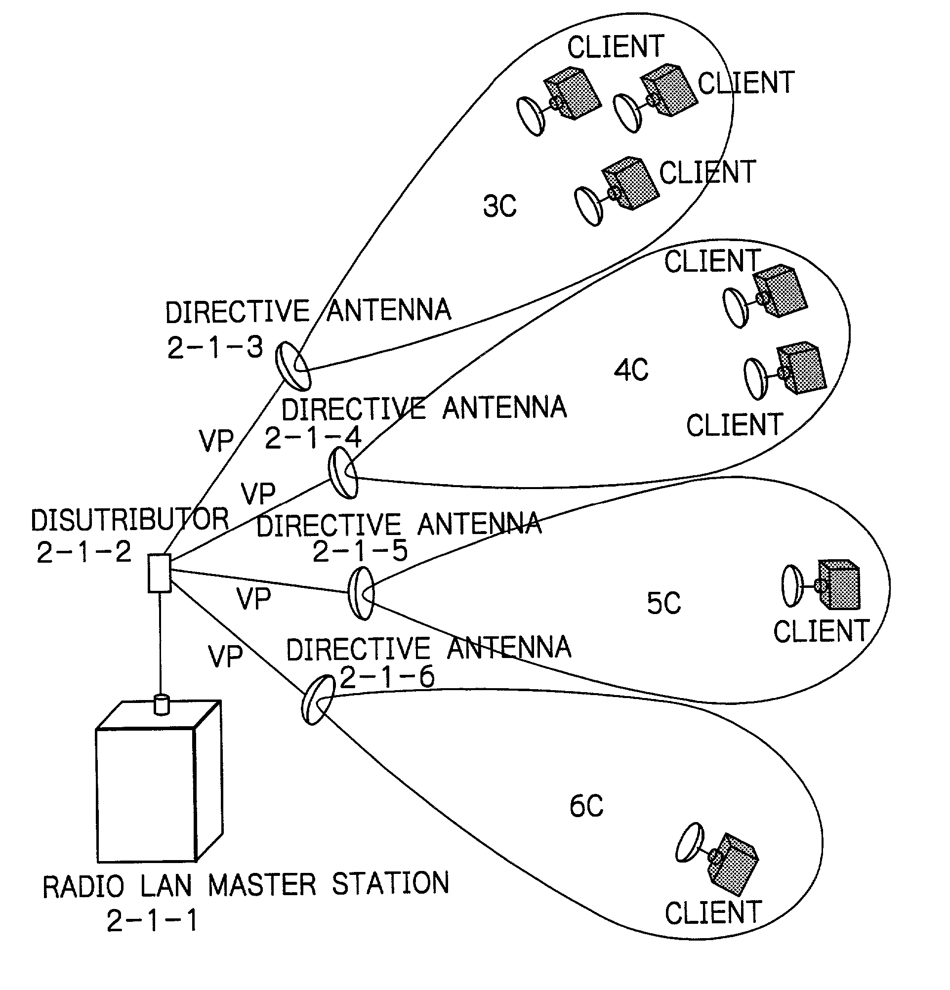
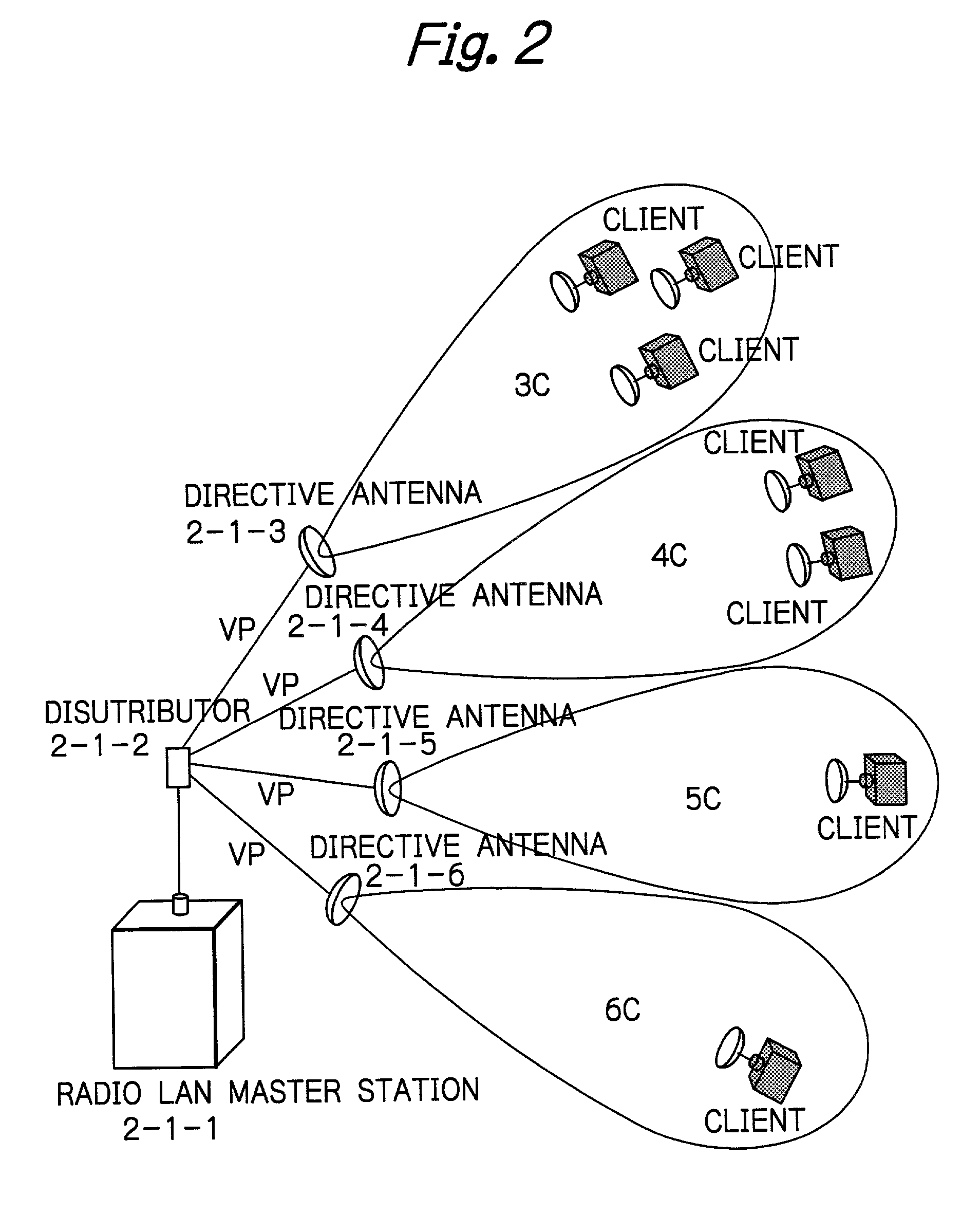
[0026] FIG. 2 shows the arrangement of a radio LAN master station according to the present invention. A master station 2-1-1 is coupled with a plurality of directivity antennas 2-1-3, 2-1-4, 2-1-5 and 2-1-6 through a power distributor 2-1-2, so that radio cells 3c-6c are provided, relating to each directivity antennas. Each antennas 2-1-3 through 2-1-6 are directed to a specific cell, and a client terminal is located in each cell. In one embodiment, radio wave emitted by each of the antennas has the common polarization, for instance, vertical polarization. The arrangement of FIG. 2 has an advantage that a long distance communication is possible, since the service area is divided into a plurality of cells and an antenna is a directivity antenna illuminating only a small cell and having large gain, although the arrangement of FIG. 1 does not have such an advantage. Further, the arrangement of FIG. 2 has an advantage that undesired interference is decreased, since no beam is directed t...
second embodiment
[0027] FIG. 3 shows the arrangement of a radio LAN master station according to the present invention. The arrangement of FIG. 3 has an advantage that a multi-path wave emitted by a client terminal directed to one of the directivity antennas but reflected by an undesirable reflection body such as a building 3-2-3, provides less interference to an adjacent antenna. The arrangement of FIG. 3 is the modification of FIG. 2, and antennas in FIG. 3 use vertical polarization and horizontal polarization alternately in angular direction, so that antennas 3-1-3 and 3-1-5 use vertical polarization, and antennas 3-1-4 and 3-1-6 use horizontal polarization. A radio wave 3-2-1 emitted by a client terminal in vertical polarization is received by an antenna 3-1-5 as a direct wave, and said radio wave is further reflected by a building 3-2-3 as a reflection wave 3-2-2, and is received by another antenna 3-1-4 which is located close to said antenna 3-1-5, and is designed to receive horizontal polariza...
third embodiment
[0028] FIG. 4 shows the arrangement of a radio LAN master station according to the present invention. The embodiment of FIG. 4 is the modification of FIG. 3, and intends to remove interference by other systems which can not remove by simple alternate arrangement of polarization as shown in FIG. 3. The embodiment of FIG. 4 has the feature that antennas 4-1-3, 4-1-4, 4-1-5 and 4-1-6 are not a strict vertical antenna, nor a strict horizontal antenna, but polarization plane of each antenna is rotated from vertical plane or horizontal plane, so that two adjacent antennas have polarizations in orthogonal relations with each other. The resultant polarization plane is fixed when the interference becomes the minimum.
[0029] The polarization plane which provides the minimum interference is determined as follows. First, the antenna which has the largest interference among all the antennas is selected. Assuming that the antenna 4-1-5 has the largest interference, the polarization plane of said a...
PUM
 Abstract
Description
Claims
Application Information