Method and system for triggering a debugging unit

Inactive Publication Date: 2002-09-12
IBM CORP
View PDF7 Cites 100 Cited by
  • Summary
  • Abstract
  • Description
  • Claims
  • Application Information

AI Technical Summary

Problems solved by technology

This is in contrast to the prior art where the marking of general instructions can initiate numerous unintended and undesirable triggers from the processor core to the debugging unit, in that the instructions subject to such marking can occur many times in the instruction stream and not just in the failing case where debugging is desired.

Method used


Image

  • Method and system for triggering a debugging unit
  • Method and system for triggering a debugging unit
  • Method and system for triggering a debugging unit

Examples


Embodiment Construction

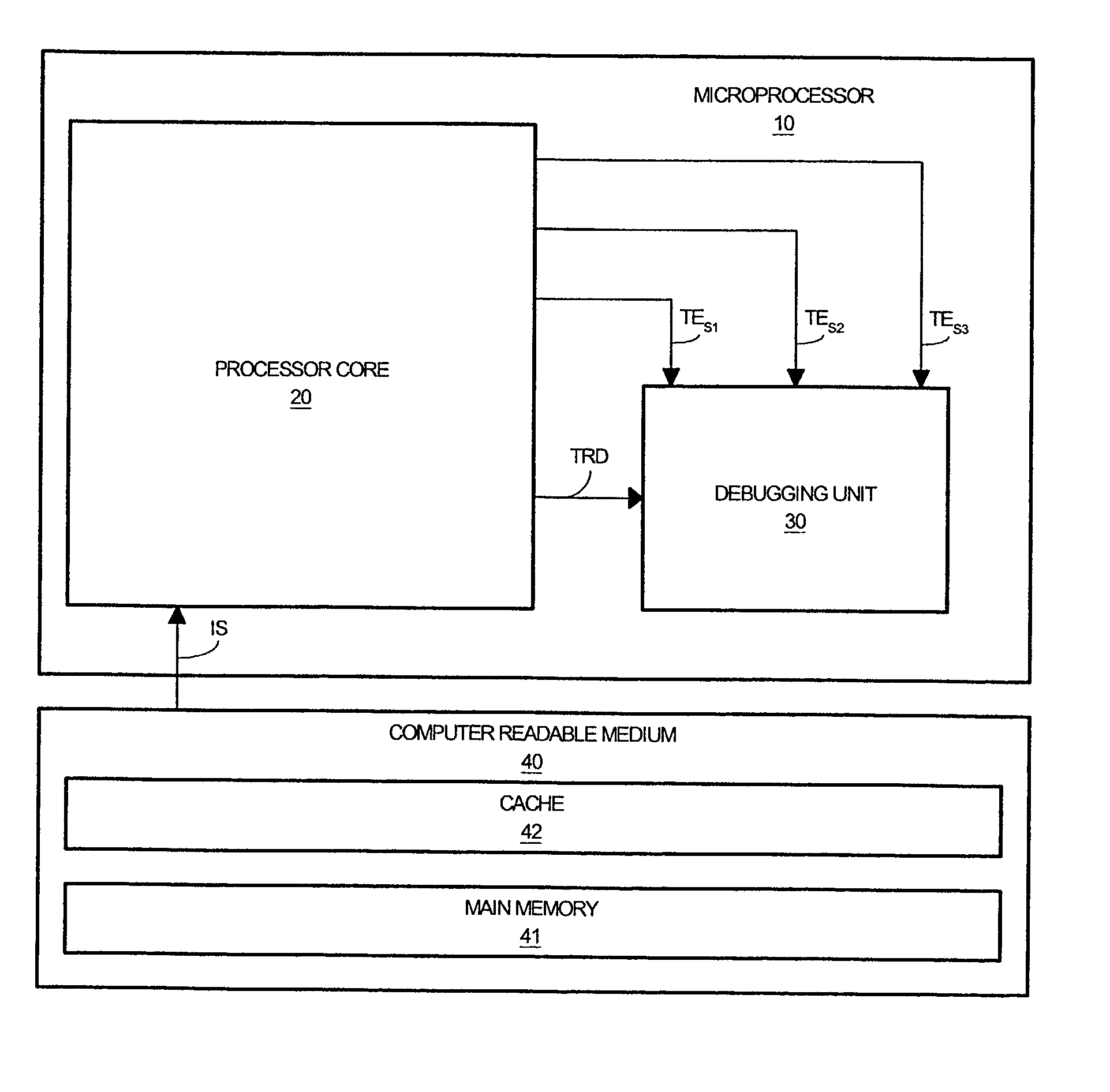
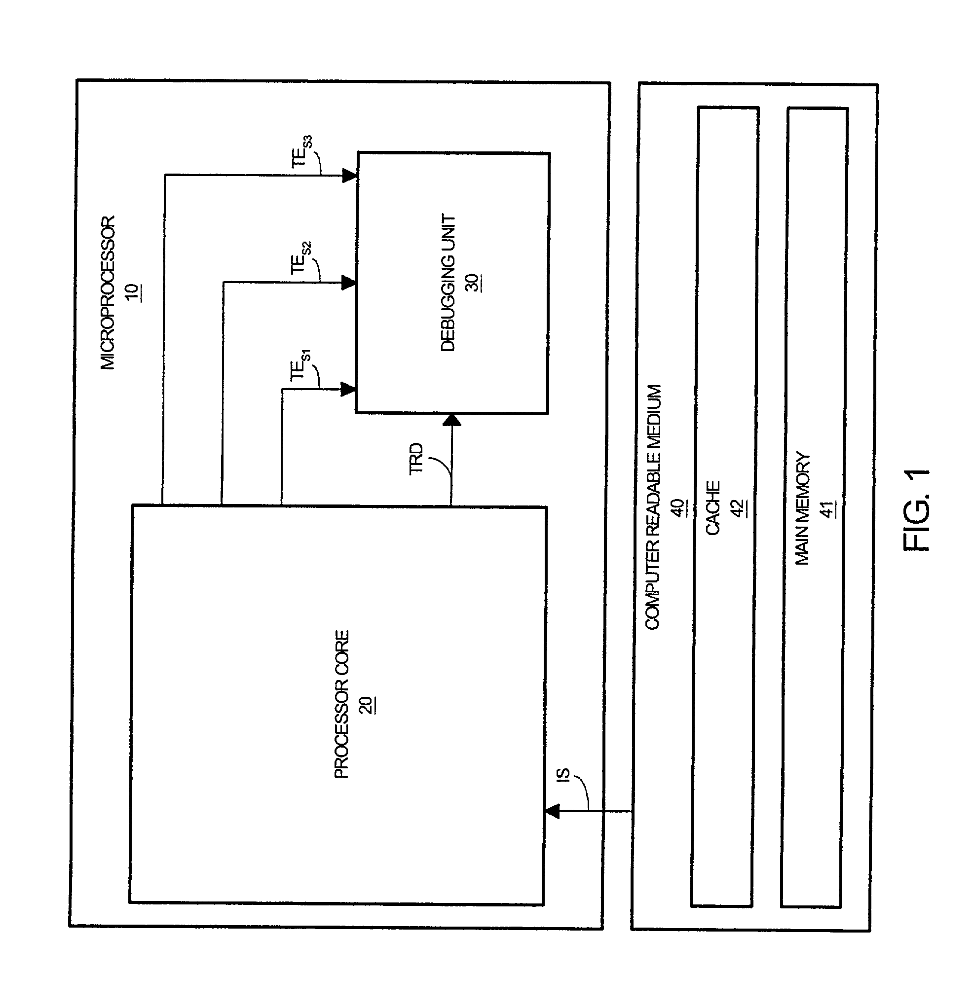
[0020] Referring to FIG. 1, a microprocessor 10 in accordance with the present invention is shown. Microprocessor 10 includes a processor core 20, and a debugging unit 30. Processor core 20 is a compilation of circuitry for fetching, decoding, and executing an instruction stream IS of operating signals from a main memory 41 and / or a cache 42 of computer readable medium 40. Processor core 20 provides trace data TRD to debugging unit 30 as the operating signals of instruction stream IS are being processed by processor core 20. Debugging unit 30 is a state machine for selectively storing trace data TRD within an internal memory component. The present invention configures processor core 20 and computer readable medium 40 in accordance with an instruction set architecture of the present invention that enables processor core 20 to provide a trigger event signal TE.sub.S1, a trigger event signal TE.sub.S2, and / or a trigger event signal TE.sub.S3 to debugging unit 30 in response to trigger ...


PUM


Abstract

A processor core for transitioning a debugging unit between a plurality of operating states in response to an instruction stream is disclosed. The processor core generates trace data as it processes operating signals of the instruction stream. The processor core provides a first trigger event signal to the debugging unit in response to a first trigger instruction signal within the instruction stream that is representative of a triggering instruction to transitions the debugging unit to a base operating state. The processor core provides a second trigger event signal to the debugging unit in response to a second trigger instruction signal within the instruction stream that is representative of a triggering instruction to dynamically store trace data within the memory component of the debugging unit. The processor core provides a third trigger event signal to the debugging unit in response to a third trigger instruction signal within the instruction stream that is representative of a triggering instruction to statically store trace data within the memory component of the debugging unit. Concurrently or alternatively, the processor core can provide one or more of the trigger event signals to the debugging unit as a function of a generated trigger data in response to additional operational instructions within the instruction stream.

Description

BACKGROUND OF THE INVENTION[0001] 1. Field of the Invention[0002] The present invention generally relates to triggering a debugging unit, and in particular, a microprocessor configured in accordance with an instruction set architecture for transitioning a debugging unit between a plurality of operating states as directed by trigger instruction signals within an instruction stream.[0003] 2. Description of the Related Art[0004] The arrangement of components on an integrated circuit increases in complexity with each improvement in the manufacturing capability of constructing additional transistors onto smaller chips. Thus, in order to meet market demand, adequate and timely testing and debugging of integrated circuits has become a priority.[0005] Currently, there exist several methods of testing and debugging components of an integrated circuit by controlling and / or monitoring a storage of trace data by a debugging unit. One method includes marking instruction addresses of a sequence o...

Claims


Application Information

Patent Timeline
Patent Type & Authority Applications(United States)
IPC IPC(8): G06F11/26
CPCG06F11/261
Inventor FLOYD, MICHAEL S.JORDAN, PAUL J.LEITNER, LARRY S.
Owner IBM CORP
Why Eureka
Try Eureka