Pipe shaver

a shaver and pipe technology, applied in the field of pipe shavers, can solve the problems of poor repeatability of obtaining a good clean oxide free surface prior to welding a connecting sleave onto the end of the pipe, poor quality control,

Inactive Publication Date: 2002-09-19
OSWALD FRITZ
View PDF2 Cites 40 Cited by
  • Summary
  • Abstract
  • Description
  • Claims
  • Application Information

AI Technical Summary

Benefits of technology

0018] Preferably wherein said mounting means micludes a blade guide for positioning a front face of said cutting blade at an angle theta of not less than 95 degrees relative to the pipe surface.
0019] Preferably wherein said mounting means includes a blade guide for positioning a front face of said cutting blade at an angle theta not less than 114 degrees and not more than 120 degrees.

Problems solved by technology

Unfortunately, the effectiveness of these methods and the repeatability of obtaining a good clean oxide free surface prior to welding of a connecting sleave onto the end of the pipe has been rather poor.
This leads to quality control issues in regard to the repeatability in preparing a good clean oxide free surface for welding of connecting sleeves onto the ends of plastic pipes.
Those skilled in the art are aware that leaks in natural gas pipe lines cannot be tolerated and can lead to disastrous consequences.
The disadvantage of all the above-mentioned devices is that they are unable to absorb any of the pipes extra thick portions or defective ovalization or out of roundness of the pipe.
In other words, these devices do not make it possible to lift off a shaving or a very small portion of the out diameter thickness of the pipe regardless of the pipes deformations which include ovalization, thickness variations and / or outer deflections.
Unfortunately, in practise this device is unable to remove a very thin consistent showing in a uniform manner around the outer diameter of a pipe regardless of the deformities and / or ovalizations in the pipe.
As well due to the complicated mechanical construction of the device it is difficult and time consuming to use and prone to mechanical breakdowns in the field.

Method used


Image

  • Pipe shaver
  • Pipe shaver
  • Pipe shaver

Examples


Embodiment Construction

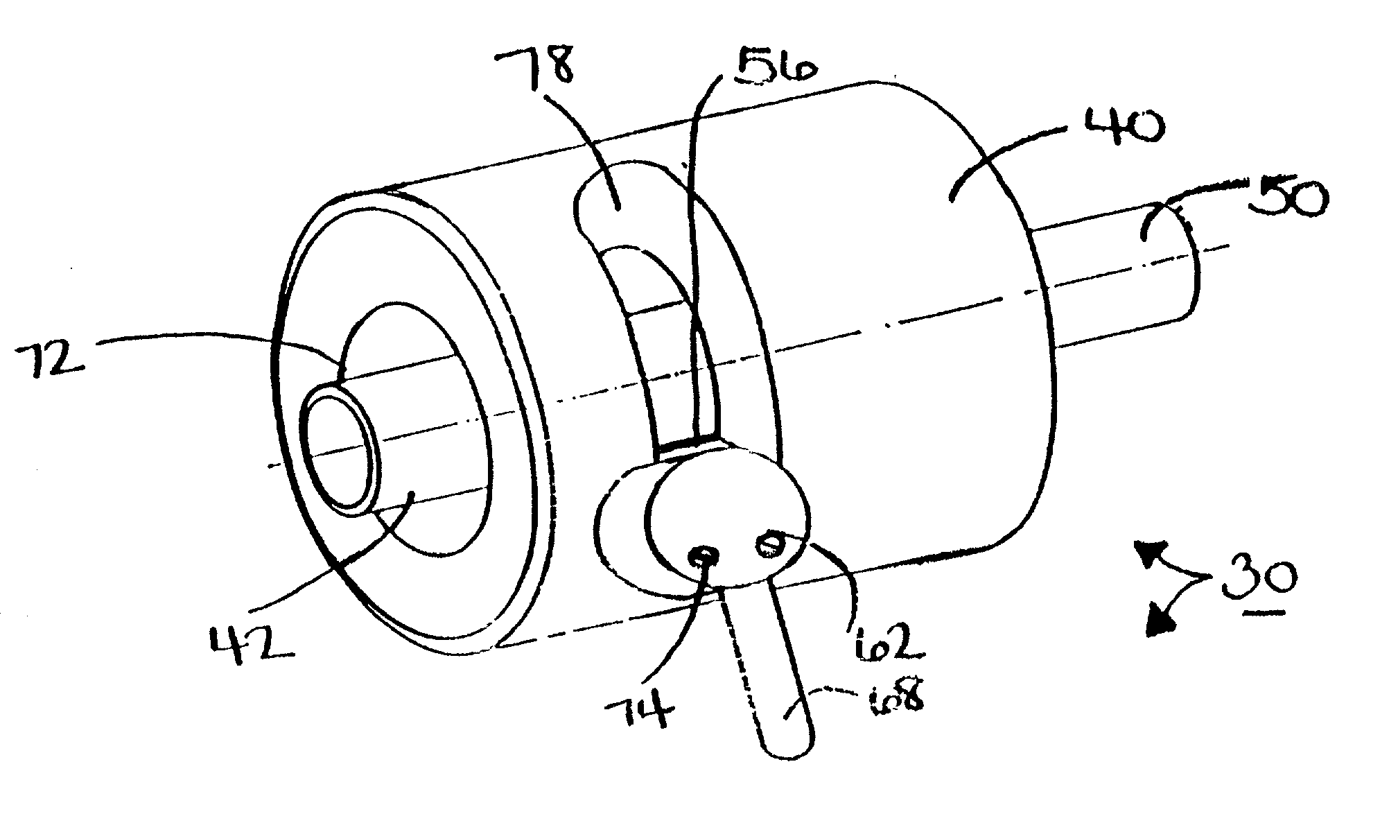
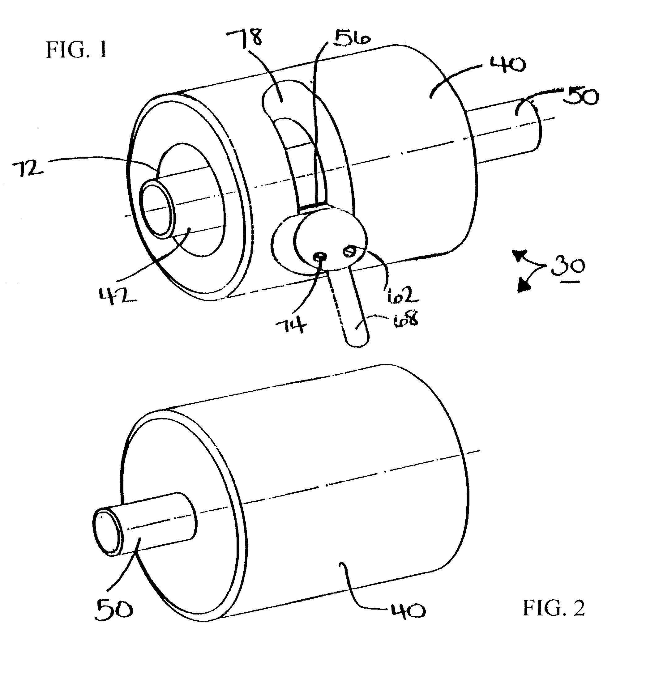
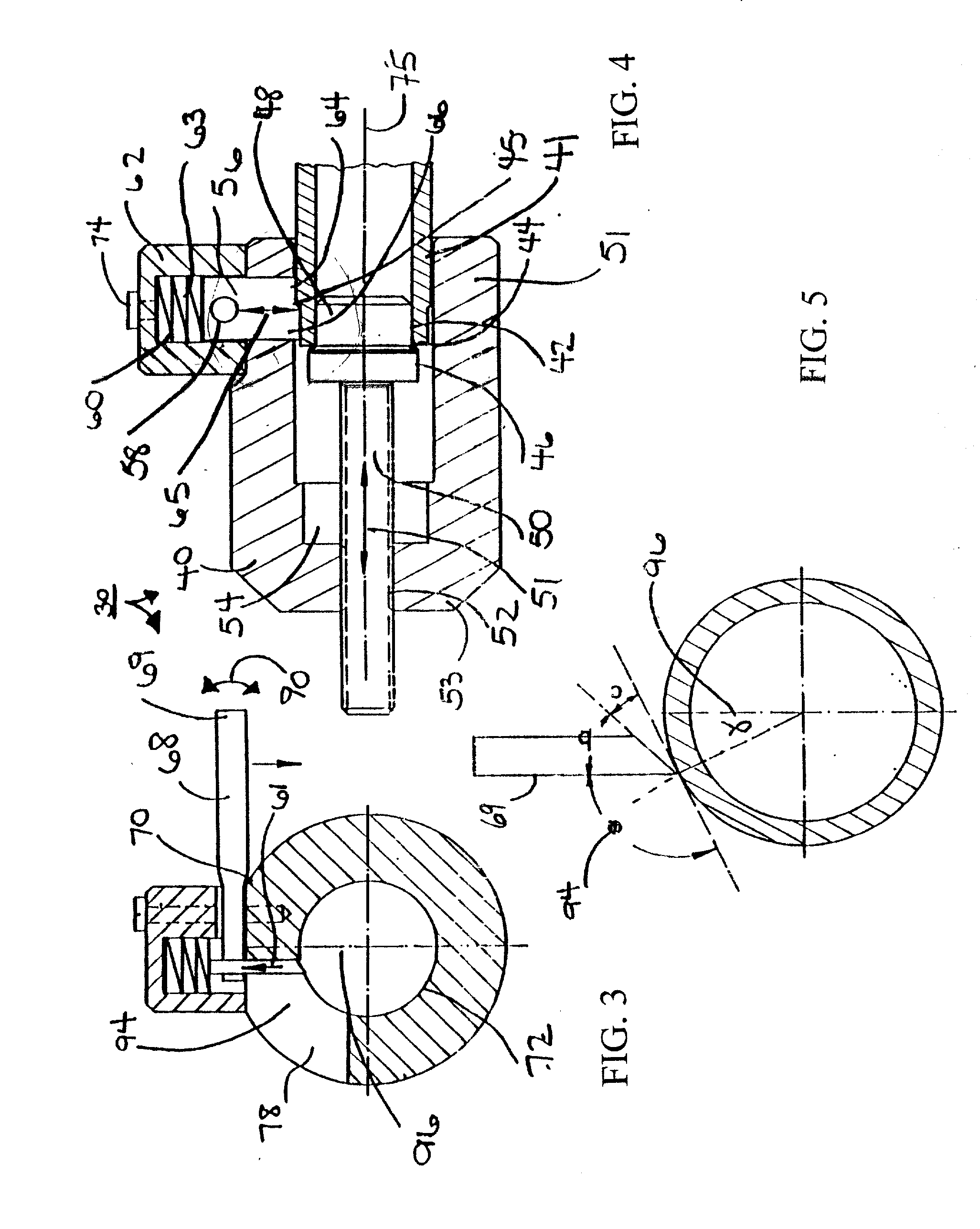
[0043] Referring to FIGS. 1, 2, 3 and 4 the present invention a pipe shaver shown generally as 30 includes the following components: a cylindrical body 40 having mounted therein a threaded shaft 50 which was mounted on one end thereon a mandrel 42. Cylindrical body 40 further includes a blade housing 62 having a cutting blade 56 mounted therein for engagement with a pipe 41.

[0044] Cylindrical body 40 generally has a cylindrical shape with a pipe receiving aperture 72 in the front portion 51 of cylindrical body 40. The rear portion 53 of body 40 is generally closed off having defined therein a threaded aperture 52.

[0045] Threaded aperture 52 co-operates with threaded shaft 50 such that when threaded shaft 50 is rotated about longitudinal axis 75, it threadably engages with threaded aperture 52 thereby longitudinally moving inwardly or outwardly along direction 51.

[0046] One end of threaded shaft 50 has mounted proximate one end a mandrel 42. Mandrel 42 includes a pipe receiving secti...


PUM

PropertyMeasurementUnit
angle thetaaaaaaaaaaa

Abstract

The present invention a pipe shaver a pipe shaver for removing a uniform layer of material from the outer diameter of a pipe, the pipe shaving includes a housing including a longitudinal axis; a cutting blade including a blade guide for positioning a front face of said cutting blade at an angle theta of not less than 95 degrees relative to the pipe surface and for mounting said blade to said housing, said blade including a cutting edge; a lifting means for manually urging said blade radially outwardly away from said pipe and inwardly to the outer diameter of the pipe; and a lever for manually urging said blade radially outwardly away from said pipe and a threaded cam for moving said cutting edge longitudinally along the outer diameter of said pipe for shaving a thin substantially uniform layer of material off the outer diameter of the pipe.

Description

FIELD OF THE INVENTION[0001] The invention relates generally to devices used for preparing pipe end surfaces for welding of sleaves thereon and more specifically relates to devices used for shaving a portion of the outer diameter of the end of a pipe for preparation of welding.BACKGROUND OF THE INVENTION[0002] Currently, the most popular way of transmitting natural gas is by the use of plastic pipes which are generally made of polyethylene, polyvinyl chloride or other types of plastic. These pipes are interconnected end to end by welding sleeves onto the ends of these pipes which in turn is welding onto the next length of pipe to be connected. The surfaces of the end of the pipe must be prepared to remove any trace of dirt and / or oxidation on the pipes so that a connecting sleeve can be effectively welded onto the end of a pipe. In order to remove the oxidized layer, currently the end of the pipe is prepared by either scraping manually using a sharp scraper blade and / or sanding usin...

Claims


Application Information

Patent Timeline
Patent Type & Authority Applications(United States)
IPC IPC(8): B23B5/16
CPCB23B5/168Y10T82/22Y10T82/2522
Inventor OSWALD, FRITZ
Owner OSWALD FRITZ
Why Eureka
Try Eureka