Die pickup method and die pickup apparatus

a pickup method and die technology, applied in the direction of electrical equipment, adhesives, semiconductor devices, etc., can solve the problems of method problems, weakened adhesive force, and likely damage to dies, and achieve the effect of reducing the adhesion area

Inactive Publication Date: 2002-09-19
SHINKAWA CO LTD
View PDF6 Cites 64 Cited by
  • Summary
  • Abstract
  • Description
  • Claims
  • Application Information

AI Technical Summary

Benefits of technology

[0011] Accordingly, the object of the present invention is to provide a die pickup method and pickup apparatus that allows an easy peeling of dies from an adhesive tape without applying any excessive force to dies.
[0018] thus causing an air layer to be formed between the die and the adhesive tape, thus separating the die to be picked up from the adhesive tape.

Problems solved by technology

However, this method has a problem.
When the thickness of the dies is as small as, for instance, approximately 100 .mu.m or less, the dies are likely damaged.
As a result, the adhesive force is weakened, and the die is suction-held by the suction holding surface.
Accordingly, there is danger that the die would be damaged by this pressing force.
Furthermore, in cases where the thickness of the die is small, the die cannot be reliably pushed, and there is a danger that the peeling side walls of the suction holding nozzle will ride over the upper surface of the die, thus scratching the die.
Generally, when a bonded die and an adhesive tape are separated, an extremely large force is required if this separation is accomplished by applying a force in the direction perpendicular to the adhesive surface.
Accordingly, in cases where the thickness of the die is extremely small, e.g., 50 .mu.m or less, then there is a danger that the die will be deformed and damaged together with the adhesive tape by the suction force of the suction holding stage if the adhesive force is strong.

Method used


Image

  • Die pickup method and die pickup apparatus
  • Die pickup method and die pickup apparatus
  • Die pickup method and die pickup apparatus

Examples


Embodiment Construction

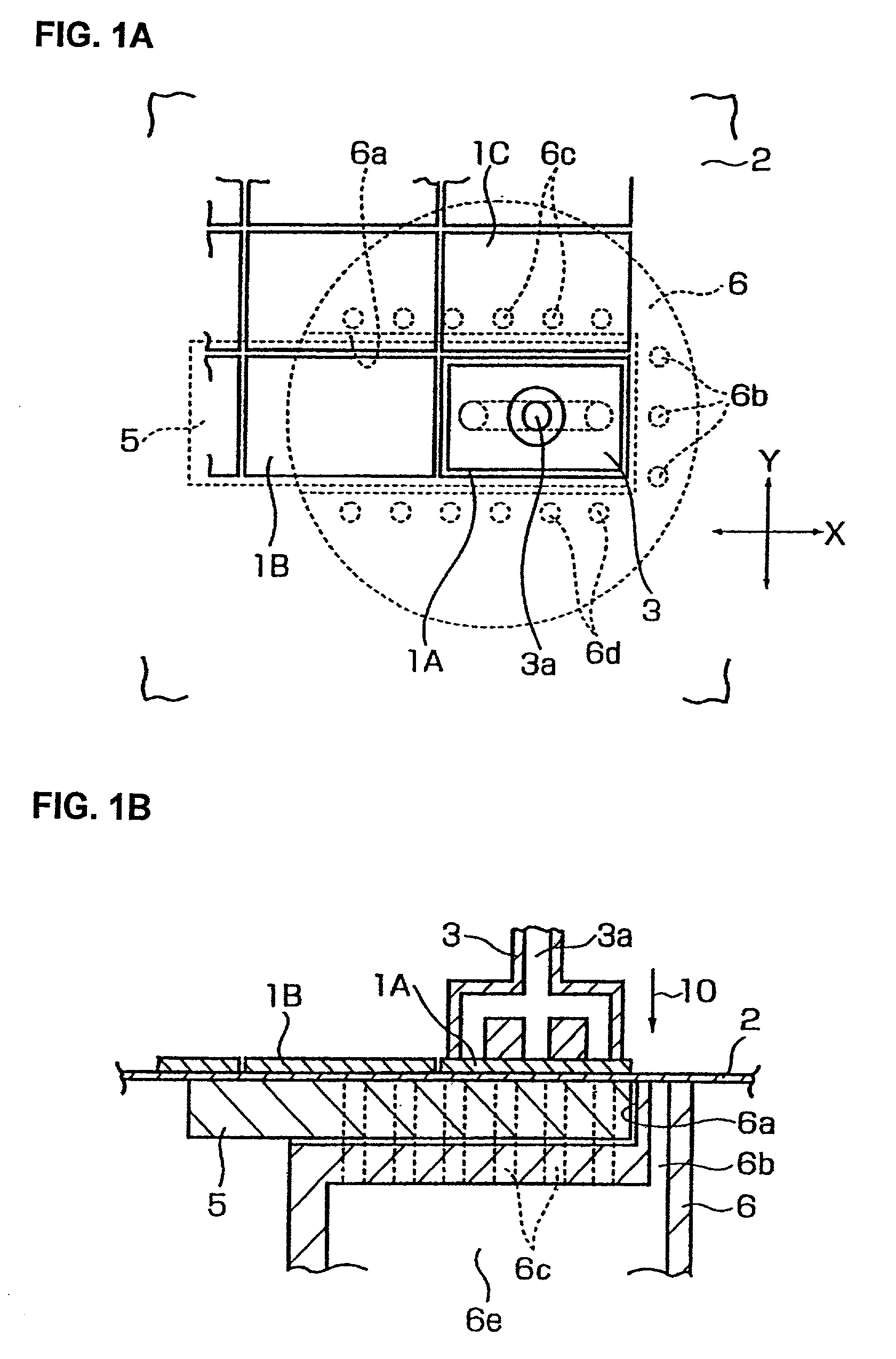
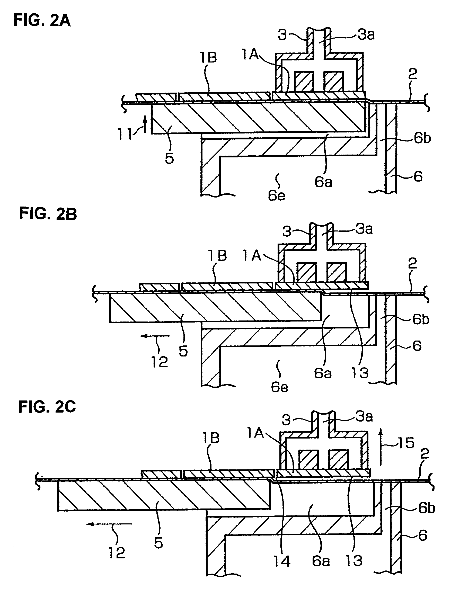
[0031] One embodiment of the present invention will be described with reference to FIGS. 1A, 1B, 2A, 2B and 2C.

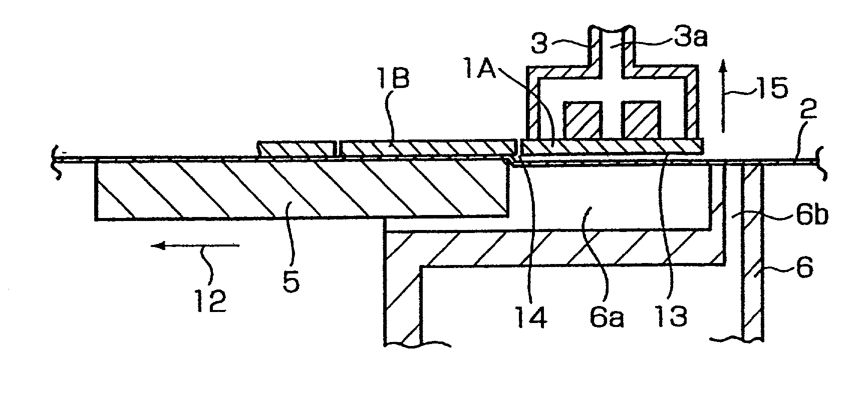
[0032] The outer circumference of an adhesive tape 2 to which dies 1A, 1B . . . are pasted is fastened to a wafer ring (not shown). The wafer ring is fastened to a wafer supporting frame (not shown) which is driven in the directions of the X and Y axes on a horizontal plane. The dies 1A, 1B . . . are held via vacuum suction and picked up by a suction holding nozzle 3 that has a suction holding hole 3a.

[0033] The reference numeral 5 is a tape peeling stage 5. The tape peeling stage 5 supports a portion of the adhesive tape 2 that corresponds to die 1A that is to be picked up in the shown embodiment. In other words, the tape peeling stage 5 supports the adhesive tape 2 that is positioned directly under the die 1A. The reference numeral 6 is a suction holding stage 6. The suction holding stage 6 holds by vacuum suction an area of the adhesive tape 2 that surrounds the die 1A t...


PUM

PropertyMeasurementUnit
thicknessaaaaaaaaaa
thicknessaaaaaaaaaa
areaaaaaaaaaaa

Abstract

A die pickup method and apparatus that uses a tape peeling stage which supports a portion of an adhesive tape that corresponds to a die to be picked up, and a suction holding stage in which suction holding holes that, with vacuum suction, holds areas of the adhesive tape that surround the die to be picked up, thus separating the die from the adhesive tape by forming an air layer between the die and the adhesive tape, and then picking up the die. The air layer is formed, with the die being held via vacuum suction by a suction nozzle provided above the suction holding stage, by raising the tape peeling stage and then by moving the tape peeling stage horizontally in a direction away from the die.

Description

BACKGROUND OF THE INVENTION[0001] 1. Field of the Invention[0002] The present invention relates to a die pickup method and apparatus that separates dies pasted to an adhesive tape from this adhesive tape and pick up such dies by a suction holding nozzle.[0003] 2. Prior Art[0004] A method that uses a push-up needle is generally employed for separating dies from an adhesive tape on which such dies have been pasted. However, this method has a problem. When the thickness of the dies is as small as, for instance, approximately 100 .mu.m or less, the dies are likely damaged.[0005] As a result, methods for separating dies from an adhesive tape without using a push-up needle have been proposed as disclosed in Japanese Patent Application Laid-Open (Kokai) No. H4-148547 (called Example 1) and Japanese Patent Application Laid-Open (Kokai) No. 2000-195877 (called Example 2).[0006] In Example 1, the suction holding surface of the suction holding nozzle in which the suction holding hole that is u...

Claims


Application Information

Patent Timeline
Patent Type & Authority Applications(United States)
IPC IPC(8): H01L21/00H01L21/301H01L21/52H01L21/68H01L21/683
CPCH01L21/67132H01L21/6836H01L21/6838H01L2221/68327Y10T156/1944Y10T156/1132H01L21/52
Inventor MIMATA, TSUTOMUSUZUKI, KOHEITAGUCHI, TAKAYUKI
Owner SHINKAWA CO LTD
Why Eureka
Try Eureka