Pivot point release load adjuster assembly for use in a pull type angle spring clutch pressure plate assembly

a technology of pull-type angle spring and pressure plate assembly, which is applied in the direction of friction clutches, interengaging clutches, clutches, etc., can solve the problems of complex and expensive mechanisms, wear and tear, and difficulty in adjusting the assembly of the pull-type angle spring clutch pressure plate, so as to increase the lever ratio and reduce the release load. , the effect of great flexibility

Inactive Publication Date: 2002-09-19
CLUTCH AUTO
View PDF0 Cites 0 Cited by
  • Summary
  • Abstract
  • Description
  • Claims
  • Application Information

AI Technical Summary

Benefits of technology

0009] The present invention relates to pivot point release load adjuster assembly for use in a pull type angle spring clutch pressure plate assembly wherein a novel assembly has been brought out to give greater flexibility in varying the axial load and in turn the release load to any desired configuration. A pin means and a cradle means have been devised so as to enable a swiveling movement of the cradle means on which the housing end of the pressure springs are mounted. The pin means is connected to the housing of the clutch assembly and the swiveling end of the pin means is having a pivoted contact surface on the cradle on which the springs are swivelingly mounted. This swiveling mechanism helps in obtaining the desired pivot point at a desired distance away from the spring seat on the swiveling end. The possibility of achieving the pivot point at such desired point away from the spring seat results in an increase in the lever ratio, consequently the release load is decreased and the pedal pressure is lowered. T

Problems solved by technology

Consequently the operator of an automobile vehicle is required to exert a high amount of pressure on the clutch pedal frequently at the time of changing gears resulting in discomfort and fatigue after continuous driving for long durations.
There are many examples of prior art pedal pressure m

Method used


Image

  • Pivot point release load adjuster assembly for use in a pull type angle spring clutch pressure plate assembly
  • Pivot point release load adjuster assembly for use in a pull type angle spring clutch pressure plate assembly
  • Pivot point release load adjuster assembly for use in a pull type angle spring clutch pressure plate assembly

Examples


Embodiment Construction

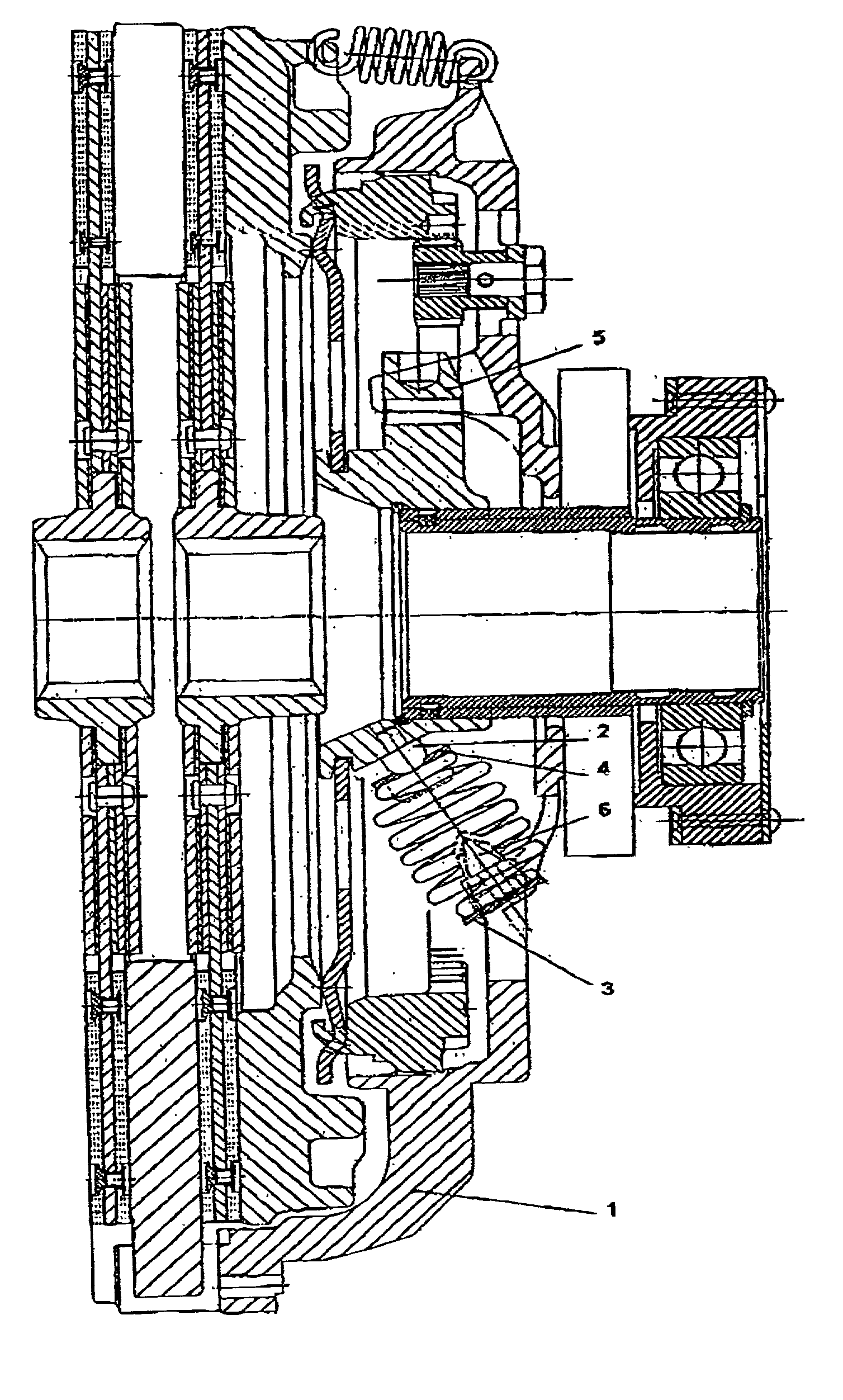
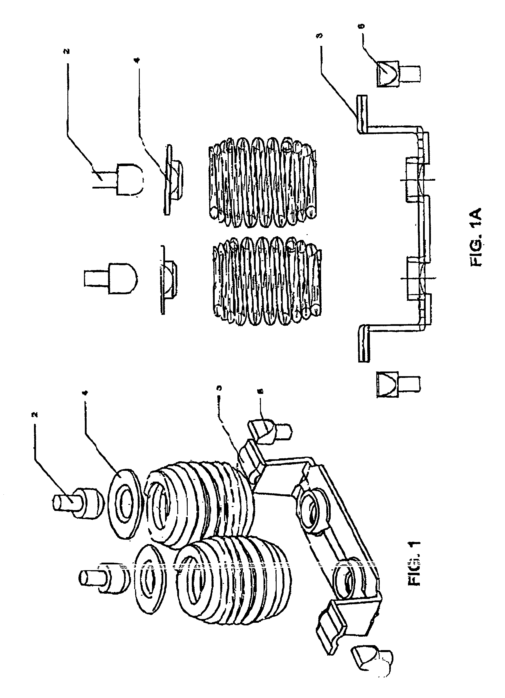
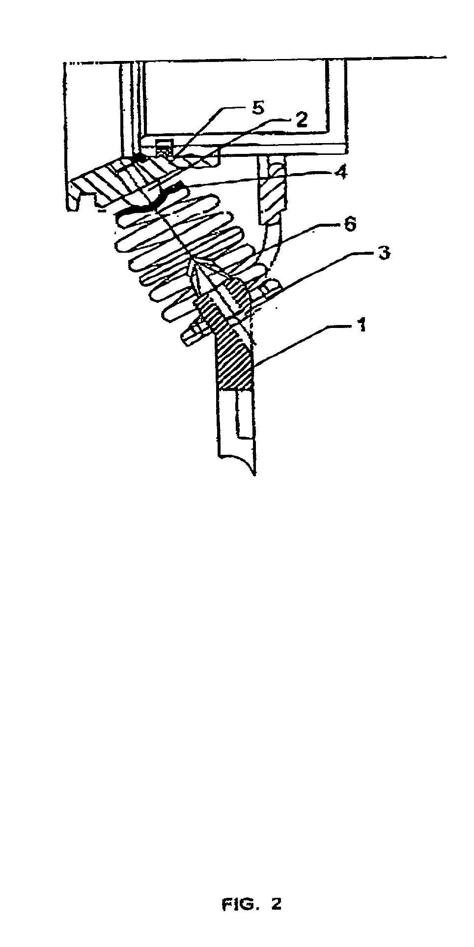
[0017] Referring now to the drawings, there is illustrated in FIG. 1. FIG. 1A and FIG. 2 a pivot point adjuster assembly. FIG. 1 is the top view of the pivot point adjuster assembly whereas FIG. 1A is the side view. FIG. 3 shows the housing [1] formed of a single piece gray cast iron. The main body of the housing [FIG. 3(1)] is generally annular in shape and is adapted to comprise the pivot point adjuster assembly [FIG. 1]. The pivot point adjuster assembly [FIG. 1 and FIG. 1A] is having the pin means [FIG. 3(6)] and is made of steel and are hardened and tempered. All pin means (six in number) are connected to the housing [FIG. 3(1)]. Pressure springs are located on the cradle [FIG. 3(4)] and it swivel about the hardened and tempered pin means [FIG. 1(6)], the bottom portion of the springs is seated on the cradle [FIG. 3(3)]. Pressure spring seat means [FIG. 3(3)]is located on release sleeve retainer pin means [FIG. 3(2)]. Pressure spring seat means are pressed from low carbon sheet...


PUM


Abstract

Pivot point release load adjuster assembly for use in a pull type angle spring clutch pressure plate assembly having a pair of pins connected to the housing end, a cradle swivelingly disposed on the said pins, a pressure spring seat swivelingly disposed on the release sleeve retainer pins and a pressure spring located between the cradle on said housing end and the pressure spring seat on said release sleeve retainer end. The cradle is operatively positioned on the said pins thereby enabling the cradle to swivel about a pivot point at a distance, between the said pressure spring seat and the said pivot point. The assembly is adapted to operatively adjust such pivot point away from the seat of the pressure spring towards the sleeve retainer end of the pressure spring whereby the desired lever ratio is achieved.

Description

BACKGROUND OF THE INVENTION[0001] 1. Field of the Invention[0002] The present invention relates to automobile clutches in general and more particularly to pivot point release load adjuster assembly for use in a pull type angle spring clutch pressure plate assembly.[0003] 2. Background of the Invention[0004] Clutches are well known mechanisms used in automobiles, which are devices adapted to typically connect a driven means and a rotational power source. The rotational power source is usually the crankshaft of an automobile engine. A clutch device is having an engaged position and a disengaged position. Typically a plurality of springs is used to move the clutch pedal from an engaged position to a disengaged position. The plurality of springs requires a high magnitude of force to be exerted on the clutch pedal for arriving at the disengaged position. Consequently the operator of an automobile vehicle is required to exert a high amount of pressure on the clutch pedal frequently at the...

Claims


Application Information

Patent Timeline
IPC IPC(8): F16D13/38
CPCF16D13/385
Inventor MEHTA, VIJAY KRISHANDALAL, RAM PHALSINGH, ASHOK KUMAR
Owner CLUTCH AUTO
Why Eureka
Try Eureka