Methods and apparatus for automatically transferring electrical power

Inactive Publication Date: 2002-09-19
GENERAL ELECTRIC CO
View PDF13 Cites 11 Cited by
  • Summary
  • Abstract
  • Description
  • Claims
  • Application Information

AI Technical Summary

Benefits of technology

0005] The limit switches are in fixed relationship to the mounting plates and assembly time is decreased because the limit switches are not adjusted during assembly. Additionally the unitary construction of the arc chute cover plate facilitates a reduction in assembly time versus an automatic transfer switch having a plurality of separate cover plates. The automatic transfer switch facilitates a decrease in assembly time by utilizing a pre-assembled auxiliary limit swit

Problems solved by technology

Automatic transfer switches are in widespread use in hospitals, military installations, industrial sites, and commercial buildings where even brief power interruptions can be cost

Method used


Image

  • Methods and apparatus for automatically transferring electrical power
  • Methods and apparatus for automatically transferring electrical power
  • Methods and apparatus for automatically transferring electrical power

Examples


Embodiment Construction

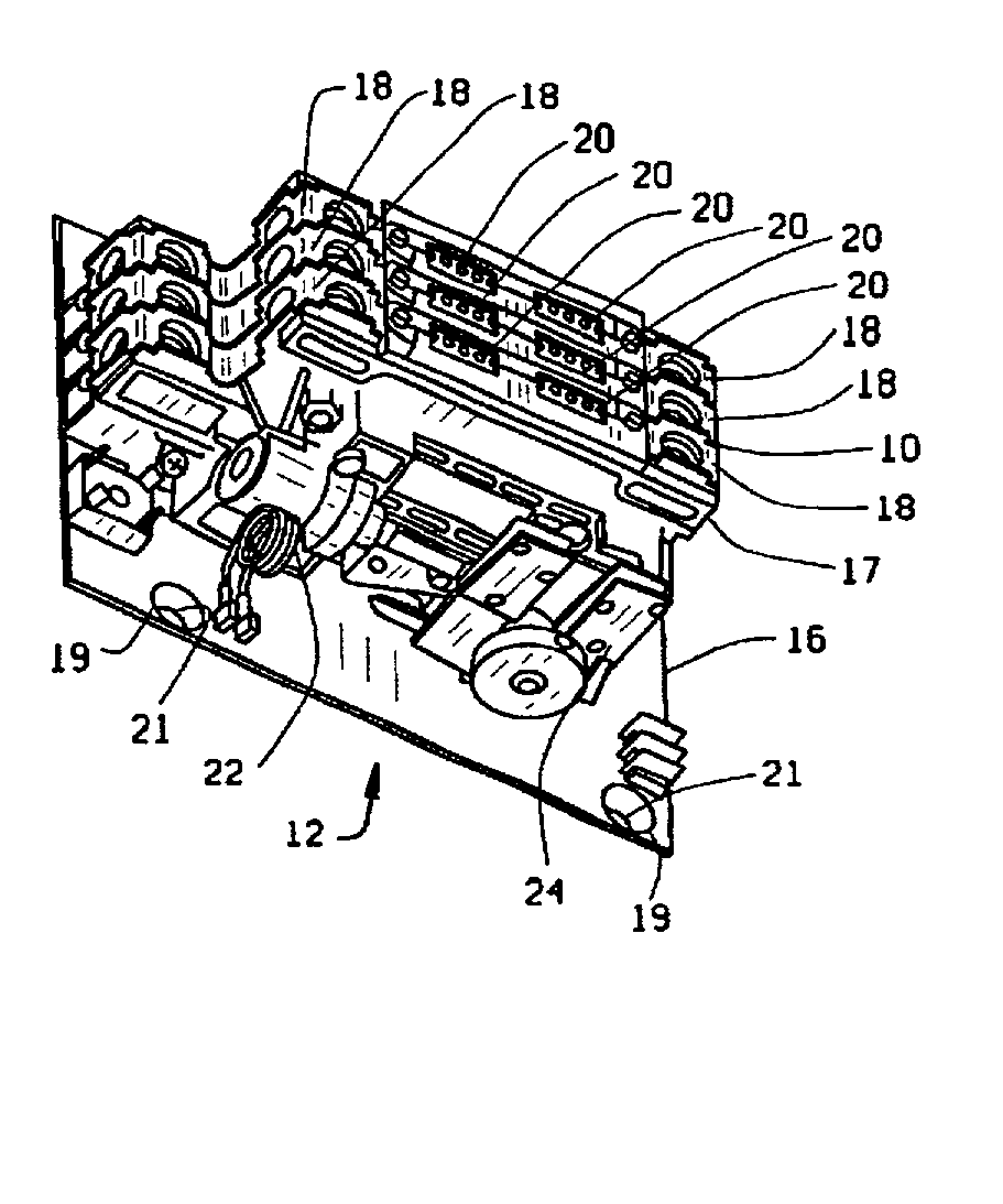
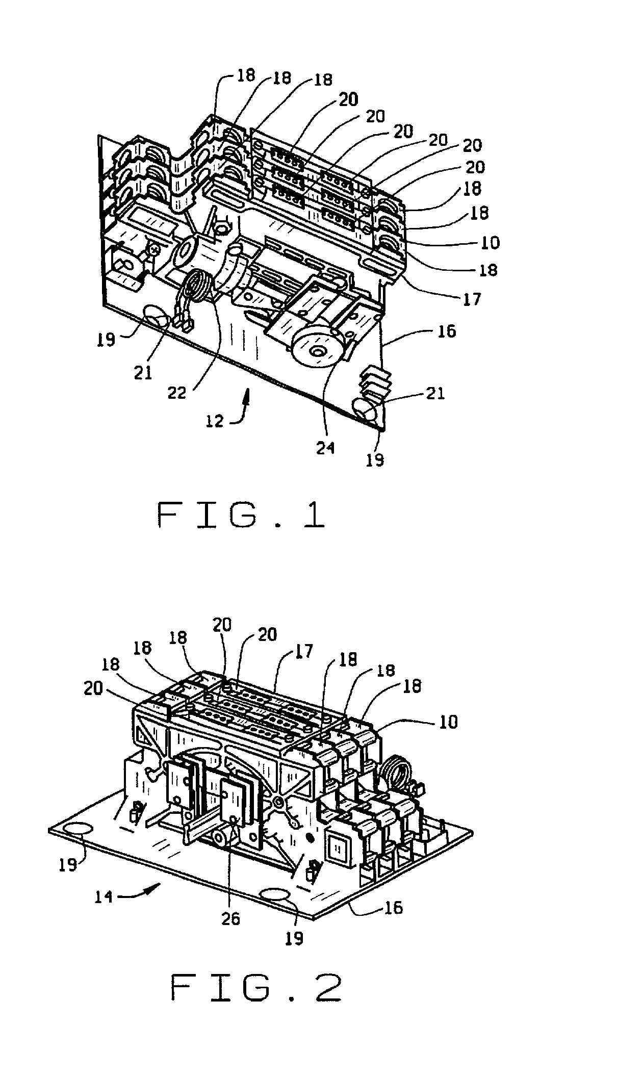
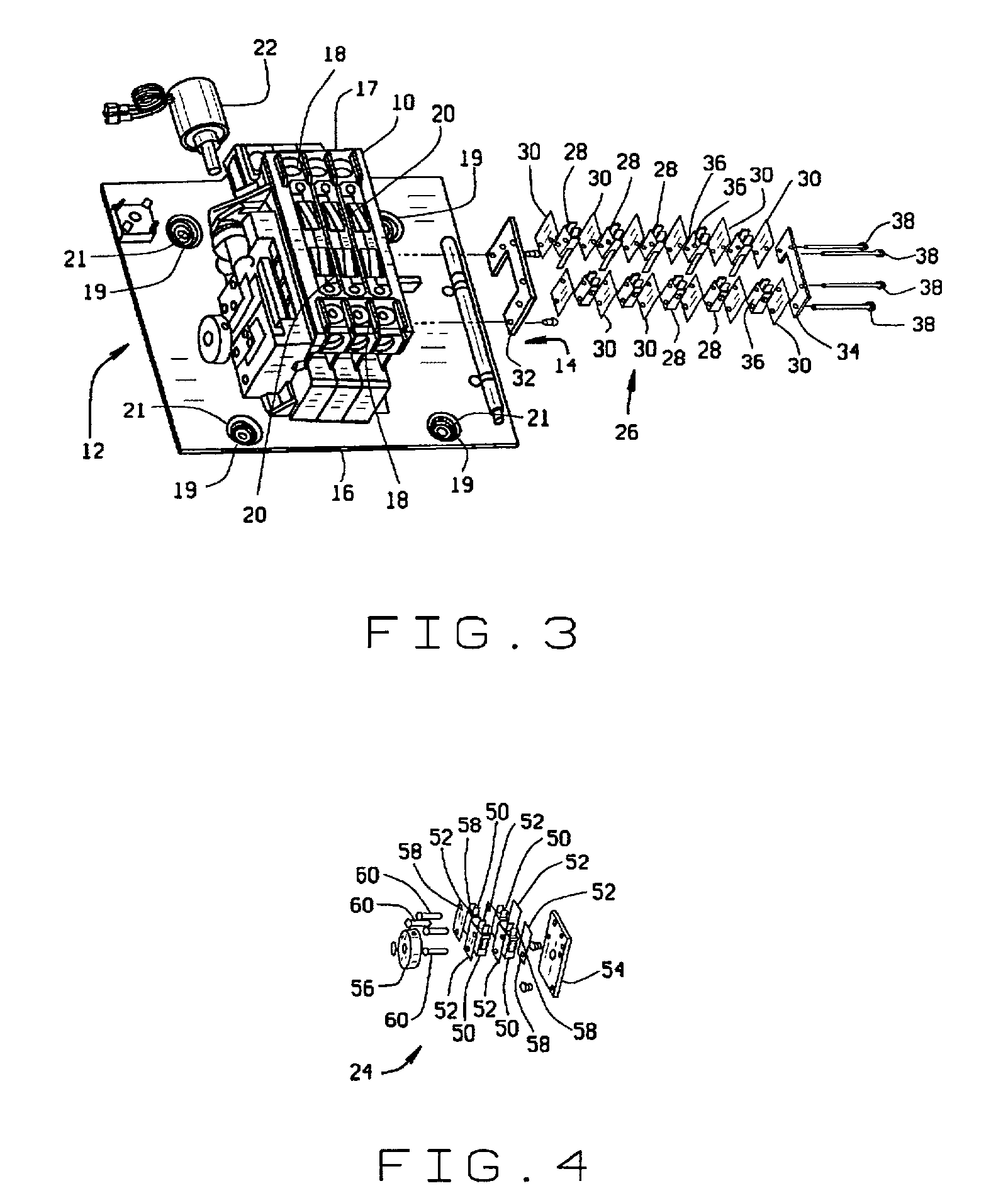
[0013] FIG. 1 is a perspective view of one embodiment of an automatic transfer switch 10 including a solenoid side 12 and FIG. 2 is a perspective view of transfer switch 10 illustrating an auxiliary side 14 of transfer switch 10. Transfer switch 10 is mounted to a mounting plate 16 and includes a main body 17 including a plurality of bus assemblies 18 electrically connected to a plurality of phase plates 20. Mounting plate 16 includes a plurality of mounting depressions 19 each including a mounting opening 21 substantially centered therein. Mounting depressions 19 are generally semispherically shaped. On solenoid side 12, transfer switch 10 includes a solenoid 22 and a solenoid side limit switch assembly 24. On auxiliary side 14, transfer switch 10 includes an auxiliary side limit switch assembly 26.

[0014] FIG. 3 is a partially exploded view of transfer switch 10. Auxiliary side limit switch assembly 26 includes a plurality of limit switches 28 interspersed with a plurality of space...


PUM


Abstract

An automatic transfer switch includes a main body having a solenoid side and an auxiliary side. A solenoid side limit switch assembly is mounted to the solenoid side and an auxiliary side limit switch assembly is mounted on the auxiliary side. The solenoid side limit switch assembly includes a plurality of limit switches and a solenoid side mounting plate. The auxiliary side limit switch assembly includes a plurality of limit switches and an auxiliary side mounting plate.

Description

BACKGROUND OF INVENTION[0001] This invention relates generally to electrical power transfer and, more particularly, to automatic transfer switches.[0002] An automatic transfer switch provides a continuous source of power for critical loads by automatically transferring from a normal power source to an emergency power source when the normal power source falls below a preset limit. Automatic transfer switches are in widespread use in hospitals, military installations, industrial sites, and commercial buildings where even brief power interruptions can be costly. Automatic transfer switches are also common to the power industry. Typical automatic transfer switches include a plurality of mechanical switching components controlled to minimize any interruptions during switching operations. Control of the switching components occurs through a series of sensing relays, transformers, and actuators, such as solenoids or linear motors to facilitate timely transfer from normal to emergency power...

Claims


Application Information

Patent Timeline
IPC IPC(8): H01H9/00
CPCH01H9/0066H01H2300/018
Inventor MILMAN, SHELDONSERRANO, MARK A.
Owner GENERAL ELECTRIC CO
Why Eureka
Try Eureka