Valve station

A technology of valve table and platen, which is applied in the field of valve table, can solve the problems of high manufacturing cost, etc., and achieve the effect of reducing manufacturing time and flexible fastening possibility

Active Publication Date: 2016-01-06
ROBERT BOSCH GMBH
View PDF5 Cites 1 Cited by
  • Summary
  • Abstract
  • Description
  • Claims
  • Application Information

AI Technical Summary

Problems solved by technology

The associated manufacturing effort is enormous, since after cutting the used components, welding is often additionally required in most cases and a rust-proof coating by painting is always required.
This leads to increased manufacturing times and thus increased delivery times

Method used


Image

  • Valve station
  • Valve station

Examples


Embodiment Construction

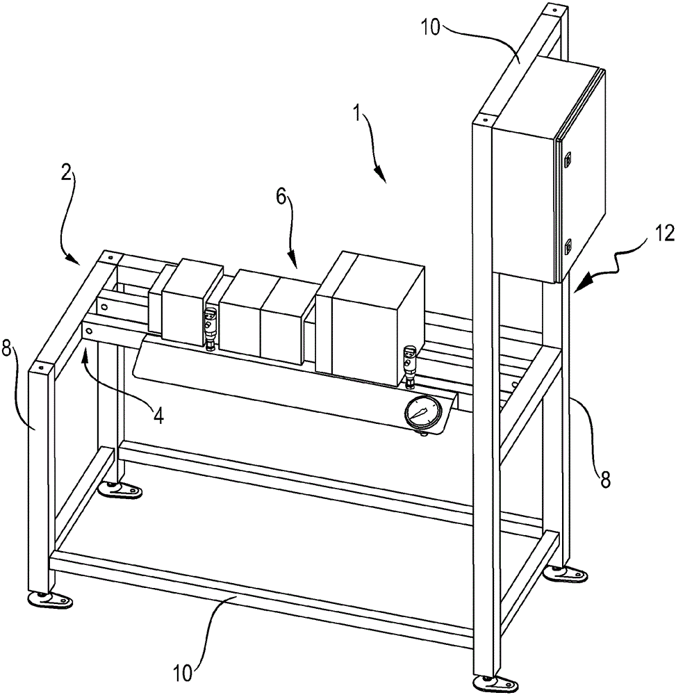
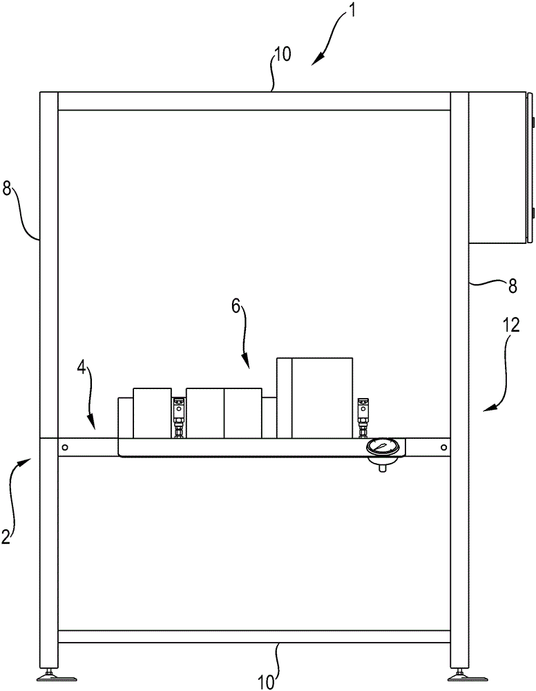
[0022] exist figure 1 The valve table 1 shown in contains a frame 2 in which a table 4 is mounted. The frame 2 is here U-shaped, ie open on one side, but can of course also be closed according to an embodiment not shown.

[0023] A hydraulic control element 6 is mounted on the table 4 and is connected to a control mechanism not shown. Shown is the coupling of the hydraulic control element 6 as it is known as the applicant's AGEV block or as the IH20 coupling.

[0024] Not only the frame 2 but also the deck 4 are formed from aluminum system profiles, in this case from the same type. In other, not shown, exemplary embodiments, other types of aluminum system profiles than those used for the deck 4 can be used for the frame 2 . The platen 4 and the frame 2 are located in a plane.

[0025] Said deck 1 is erected on the basis of legs 8 made of said aluminum system profile. In order to improve the stability, the legs 8 are connected in the region of their ends to a crossbar 10 ....


PUM


Abstract

Disclosed is a valve station with a frame and a platen is mounted. A hydraulic and / or pneumatic control component is disposed on the platen and / or the frame, and the hydraulic and / or pneumatic control component is connected with a control organ. The valve station is made from aluminium system profiles.

Description

technical field [0001] The invention relates to a valve station according to the preamble of claim 1 . Background technique [0002] Today, the valve tables available on the market are almost exclusively available in steel construction. The manufacturing effort associated with this is enormous, since after cutting the components used, in most cases welding is additionally required and a rust-proof coating by painting is always required. This leads to increased production times and thus increased delivery times. Contents of the invention [0003] In contrast, the object of the present invention is to provide a valve station for which the production time and thus the delivery time are shortened. [0004] This object is solved by a valve table having the features of patent claim 1 . [0005] Advantageous developments of the valve station according to the invention are described in the further subclaims. [0006] The valve table according to the invention comprises a frame...

Claims


Application Information

Patent Timeline
Patent Type & Authority Applications(China)
IPC IPC(8): B25H1/00
CPCB25H1/02
Inventor U.霍夫曼B.埃贝尔特T.赫夫林E.巴西克
Owner ROBERT BOSCH GMBH
Why Eureka
Try Eureka