
Vehicular passive safety device

a passive safety device and vehicular technology, applied in vehicular safety arrangments, pedestrian/occupant safety arrangements, cycle equipment, etc., to achieve the effect of easy adjustment of the height of the upper end

Inactive Publication Date: 2002-09-19
HONDA MOTOR CO LTD
View PDF7 Cites 9 Cited by
  • Summary
  • Abstract
  • Description
  • Claims
  • Application Information

AI Technical Summary

Benefits of technology

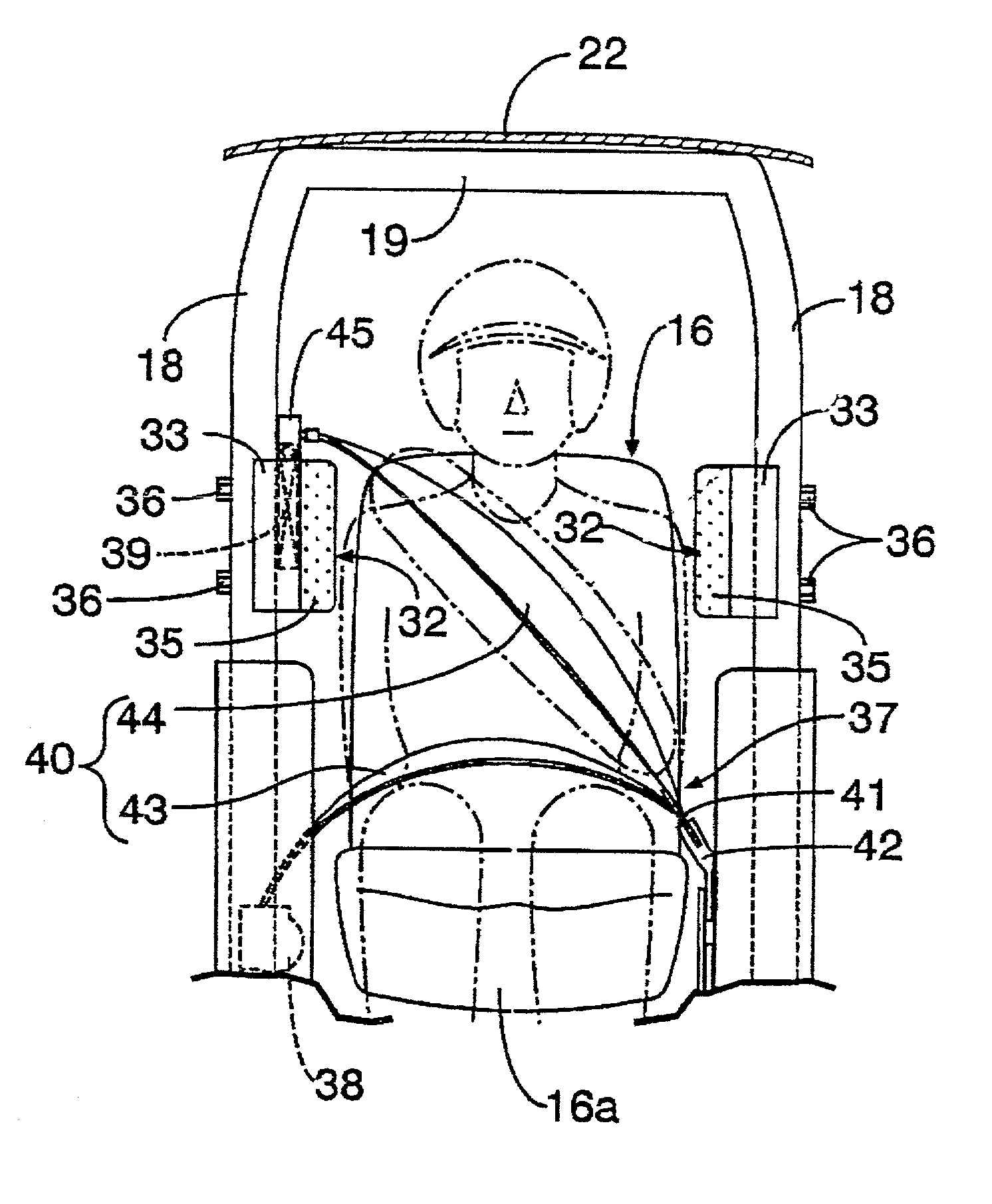
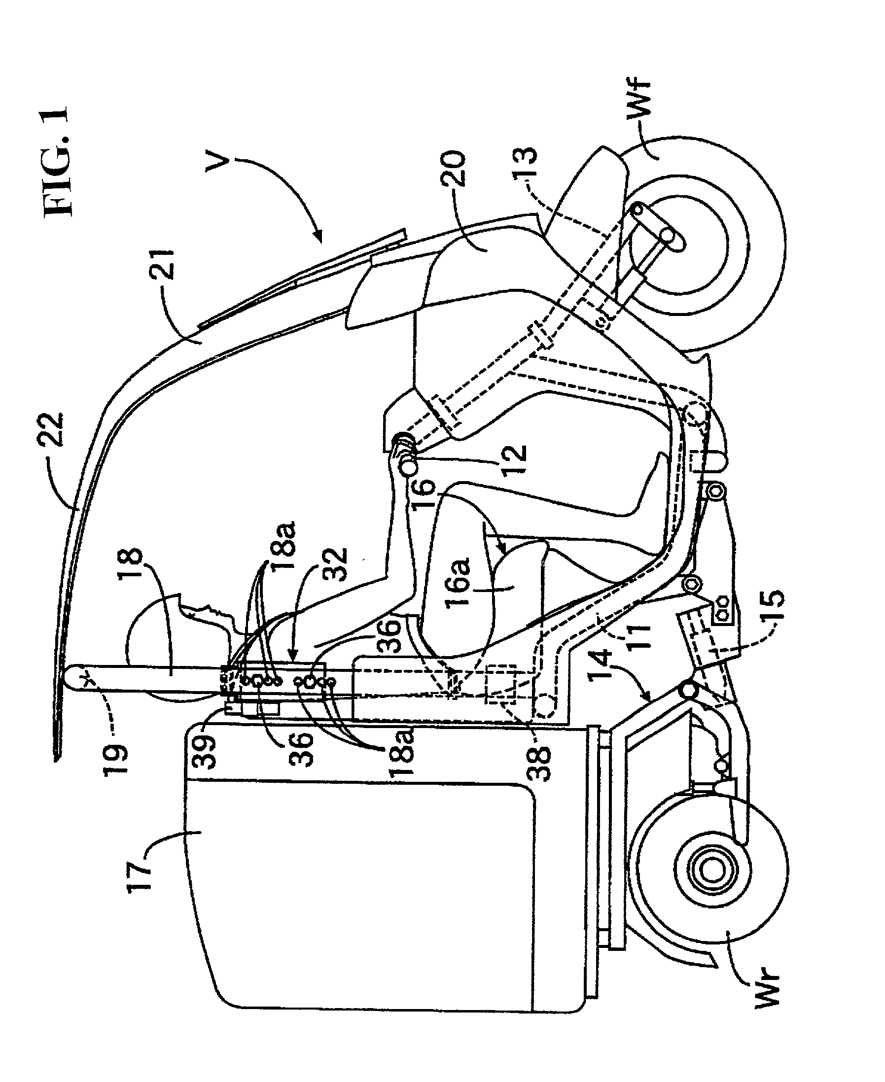
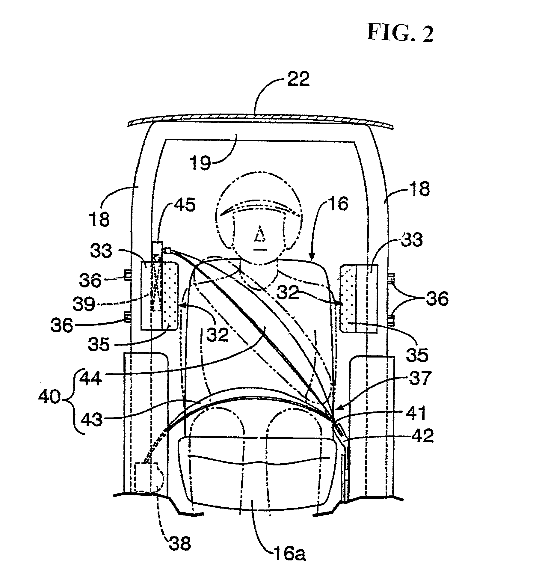
[0007] The present invention enables an easy adjustment of the height of the upper end of a shoulder belt of webbing by utilizing a shoulder guard provided on struts provided on both the right and left sides of a seat.
[0009] According to the above-mentioned configuration, as the end on the side of the shoulder belt of the webbing of the air belt system and the inflator are attached to one of the right and left shoulder guards provided to the struts on both right and left sides of the seat wherein the upper and lower positions can be adjusted, the height of the shoulder belt attached to the shoulder guard can be automatically adjusted to a suitable height in accordance with the seated height of an occupant. The height of the shoulder guard is adjusted in accordance with the seated height of the occupant. In addition, a reduction in time and labor for the adjustment occurs. As the inflator is also attached to the shoulder guard and is also vertically moved together with the shoulder belt, the positional relationship between the inflator and the shoulder belt is unchanged and a supply path of a high pressure gas from the inflator to the shoulder belt can be simplified.

Problems solved by technology

However, for the above-mentioned conventional type, the upper end of the shoulder belt and the inflator are fixed to the center pillar so that they cannot be moved.

Method used


Image

  • Vehicular passive safety device
  • Vehicular passive safety device
  • Vehicular passive safety device

Examples


Embodiment Construction

[0021] The invention will be described based upon embodiments of the invention shown in attached drawings below.

[0022] As shown in FIGS. 1 and 2, the three-wheeled vehicle V is provided with one front wheel Wf arranged in the front of the vehicle body and a pair of right and left rear wheels Wr and Wr arranged in the rear of the vehicle body. The front wheel Wf is provided at the lower end of a fork 13 connected to a bar handle 12 supported by a body frame 11 and can be steered right and left by the operation of the bar handle 12. A swing unit 14 in which an engine and a transmission are integrated is supported in the rear of the body frame 11 via a pivot 15 so that the swing unit can be swung right and left and the rear wheels Wr and Wr which are driving wheels are provided to the swing unit 14. A seat 16 on which an occupant is seated is provided over the body frame 11 and a glove compartment 17 supported on the swing unit 14 is arranged at the back of the seat 16. Two struts 18 a...


PUM


Abstract

To enable the easy adjustment of the height of the upper end of a shoulder belt of webbing utilizing a shoulder guard provided to a strut provided on both right and left sides of a seat. An air belt system is provided with webbing in which a lap belt that cannot be inflated and a shoulder belt that can be inflated are connected to each other. A retractor is provided to one side of a seat for winding the end of the lap belt. A tongue is supported in an intermediate part of the webbing so that the tongue can slide relative thereto. A buckle is provided on the other side of the seat for connecting the tongue so that the tongue can be detached. An inflator is connected to the end of the shoulder belt for supplying high pressure gas to the shoulder belt. Right and left shoulder guards are respectively provided to the struts provided on both right and left sides of the seat so that the upper and lower positions can be adjusted. The upper end of the shoulder belt and the inflator are attached to right or left shoulder guards.

Description

CROSS-REFERENCE TO RELATED APPLICATIONS[0001] The present application claims priority under 35 USC 119 to Japanese Patent Application No. 2001-058924 filed on Mar. 2, 2001 the entire contents thereof are hereby incorporated by reference.BACKGROUND OF THE INVENTION[0002] 1. Field of the Invention[0003] The present invention relates to an air belt system that inflates a part of the webbing with high pressure gas supplied from an inflator for restraining an occupant on a seat when a vehicle collides.[0004] 2. Description of Background Art[0005] An air belt system for an automobile that houses a bag inside the webbing of a seat belt and softly restrains an occupant by inflating the bag when a vehicle collides is disclosed in Japanese published unexamined patent application No. Hei 11-165605. As shown in FIG. 9, for this air belt system, the end of a shoulder belt 04 of webbing 03 is connected to an inflator 02 provided inside an automobile center pillar 01 and when the automobile collid...

Claims


Application Information

Patent Timeline
IPC IPC(8): B60R21/04B60R21/02B60R21/13B60R21/18B60R22/02B60R22/14B60R22/20B60R22/24B62J27/00
CPCB60R21/18B60R22/20B60R2022/027B62J27/10
Inventor KURATA, NORIHIROKUROE, TAKESHI
Owner HONDA MOTOR CO LTD
Learn More