Radially-oriented planar surfaces for flare reduction in panoramic cameras

a planar surface and panoramic camera technology, applied in the field ofphotographic imaging, can solve the problems of difficult to affix the mirror to the camera, inability to easily bend and optical misalignment, and weak center post support, and achieve the effect of reducing unwanted reflections

Inactive Publication Date: 2002-10-10
360AI SOLUTIONS LLC
View PDF2 Cites 21 Cited by
  • Summary
  • Abstract
  • Description
  • Claims
  • Application Information

AI Technical Summary

Benefits of technology

0013] The invention further encompasses a method of reducing unwanted reflections in a panoramic imaging system comprising the steps of mounting a convex reflector in a transparent cylinder, inserting a first radially-oriented planar member in the transparent cylinder, connecting a camera to the transparent cylinder, and using the camera to capture an image of a scene embodied in light reflected from the convex mirror. The method can further comprise the step of inserting a second radially-oriented planar member in the transparent cylinder between the convex reflector and the camera. The first and second radially-oriented planar members would preferably lie in perpendicular planes, however, they may lie in non-perpendicular planes. The cameras used in connection with this invention can be still or video cameras.

Problems solved by technology

Affixing the mirror to the camera is problematic, since any support structure must necessary appear in the device's field of view.
Furthermore, the center post support is inherently weak and prone to bending and optical misalignment.
Finally, there is the issue of mounting it to the camera.
There is no easy way to affix it to the camera other than boring through the camera's lens or affixing the post to a transparent lens attachment.
However, a "transparent" material, such as glass or plastic, is typically not 100% transparent.

Method used


Image

  • Radially-oriented planar surfaces for flare reduction in panoramic cameras
  • Radially-oriented planar surfaces for flare reduction in panoramic cameras
  • Radially-oriented planar surfaces for flare reduction in panoramic cameras

Examples


Embodiment Construction

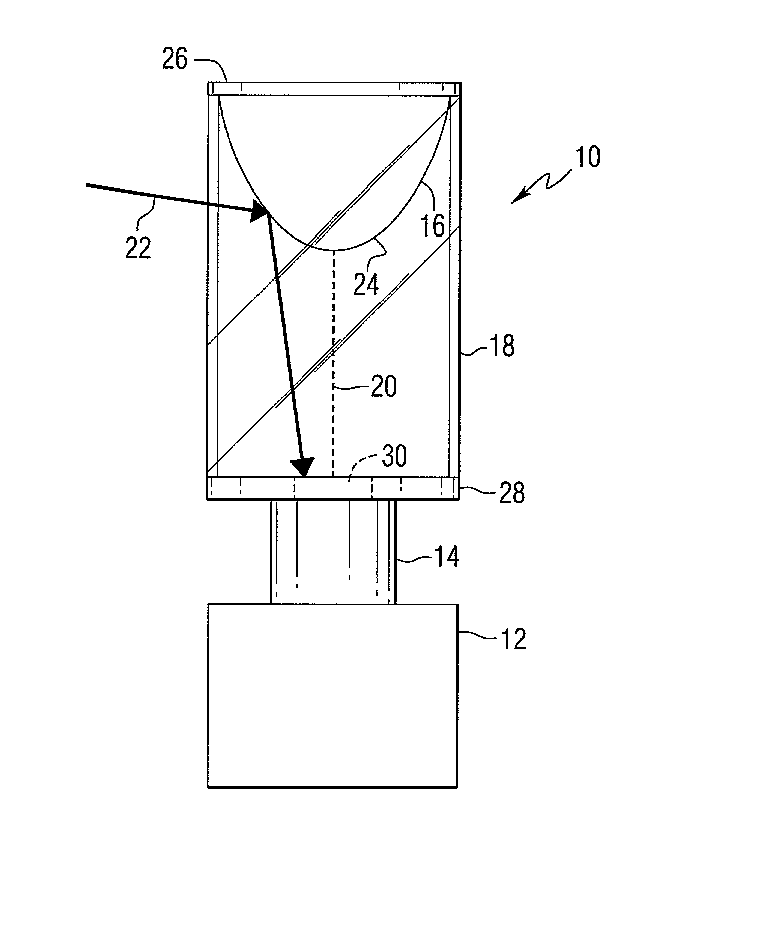
[0022] Reflective optics offer a solution to the problem of immersive imaging. A camera placed at a distance with respect to a convex reflective surface can produce a large field of view provided an appropriate mirror shape is provided. As used herein, the term "panoramic visual images" means wide-angle images taken from a field of view of up to 360.degree. around a principal axis. Such images also cover a vertical field of view may typically range from 0.1.degree. to 180.degree..

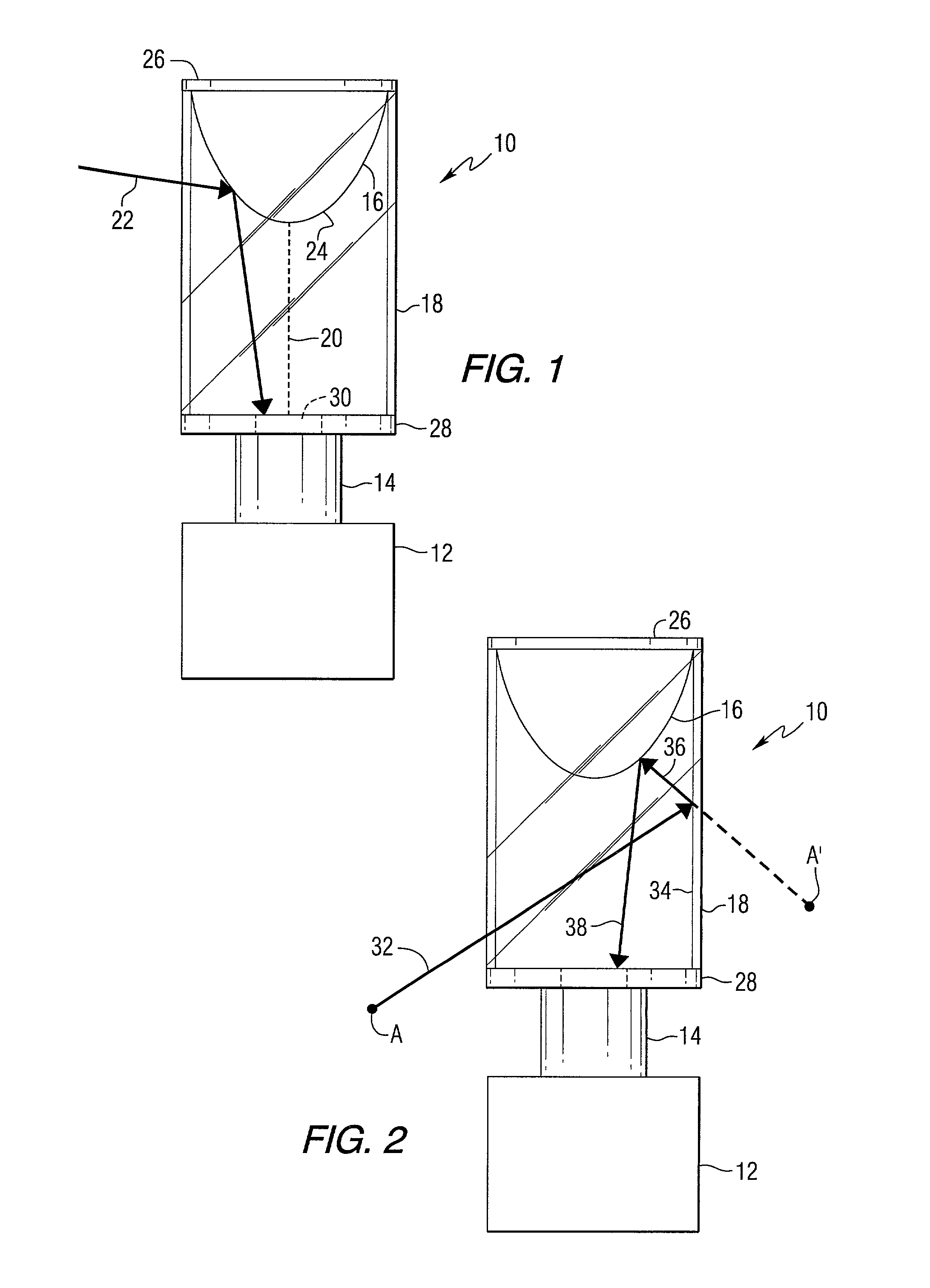
[0023] FIG. 1 is a side elevation view of a camera system 10 for producing panoramic images. The system 10 includes a still or video camera 12 having a lens 14. A reflecting surface, such as a convex mirror 16 is mounted in transparent cylinder 18 made of, for example glass or plastic. The cylinder 18 has a central axis 20. The mirror 16 gathers light 22 from all directions within a field of view and redirects it to camera 12. The mirror 16 has a profile 24, which substantially defines and describes the sha...


PUM


Abstract

A panoramic imaging system includes a convex reflector, a camera, a transparent cylinder for mounting the convex reflector to the camera, and a first radially-oriented planar member positioned in the transparent cylinder between the convex reflector and the camera. A second radially-oriented planar member can be positioned in the transparent cylinder between the convex reflector and the camera. The first and second radially-oriented planar members would preferably lie in perpendicular planes, however, they may lie in non-perpendicular planes. A mirror mount for a panoramic imaging system includes a convex reflector, a transparent cylinder for supporting the convex reflector, means for connecting a camera to the transparent cylinder, and a first radially-oriented planar member positioned in the transparent cylinder between the convex reflector and the camera. A method of reducing unwanted reflections in the panoramic imaging system is also included.

Description

CROSS-REFERENCE TO RELATED APPLICATIONS[0001] This application claims the benefit of U.S. Provisional Application Serial No. 60 / 271,157 filed Feb. 24, 2001; U.S. Provisional Application Serial No. 60 / 271,154 filed Feb. 24, 2001; and U.S. Provisional Application Serial No. 60 / 326,013 filed Sep. 27, 2001.FIELD OF THE INVENTION[0002] The present invention relates to photographic imaging, and more particularly to methods and apparatus for eliminating unwanted reflections in panoramic images.BACKGROUND INFORMATION[0003] Recent work has shown the benefits of panoramic imaging, which is able to capture a large azimuth view with a significant elevation angle. If instead of providing a small conic section of a view, a camera could capture an entire half-sphere at once, several advantages could be realized. Specifically, if the entire environment is visible at the same time, it is not necessary to move the camera to fixate on an object of interest or to perform exploratory camera movements. T...

Claims


Application Information

Patent Timeline
Patent Type & Authority Applications(United States)
IPC IPC(8): G03B17/00G03B37/00G03B37/02
CPCG03B37/00
Inventor HERMAN, HERMANSTENTZ, ANTHONYRONDINELLI, MICHAEL
Owner 360AI SOLUTIONS LLC
Why Eureka
Try Eureka