Method and system for providing dispersion and dispersion slope compensation

a technology of dispersion slope and dispersion slope, applied in the field of dispersion slope compensation, can solve the problems of limiting the ability to transmit high data rates, affecting the ability to produce dcf that simultaneously compensates the dispersion slope, and the overall propagation penalty proportional to the square of bit ra

Inactive Publication Date: 2002-10-31
CIENA
View PDF0 Cites 22 Cited by
  • Summary
  • Abstract
  • Description
  • Claims
  • Application Information

AI Technical Summary

Problems solved by technology

Dispersion has a limiting effect on the ability to transmit high data rates.
Thus, the combination of increasing spectral broadening and decreasing distortion tolerance makes the overall propagation penalty proportional to the square of bit rate.
While DCF provid...

Method used


Image

  • Method and system for providing dispersion and dispersion slope compensation
  • Method and system for providing dispersion and dispersion slope compensation
  • Method and system for providing dispersion and dispersion slope compensation

Examples


first embodiment

[0036] Exemplary embodiments for providing multiple different types of DCF will now be described. An exemplary system in the invention is shown in FIG. 3. FIG. 3 depicts an inter-network element dispersion compensation approach and FIG. 4 depicts a span-based, terminal-to-terminal dispersion compensation approach.

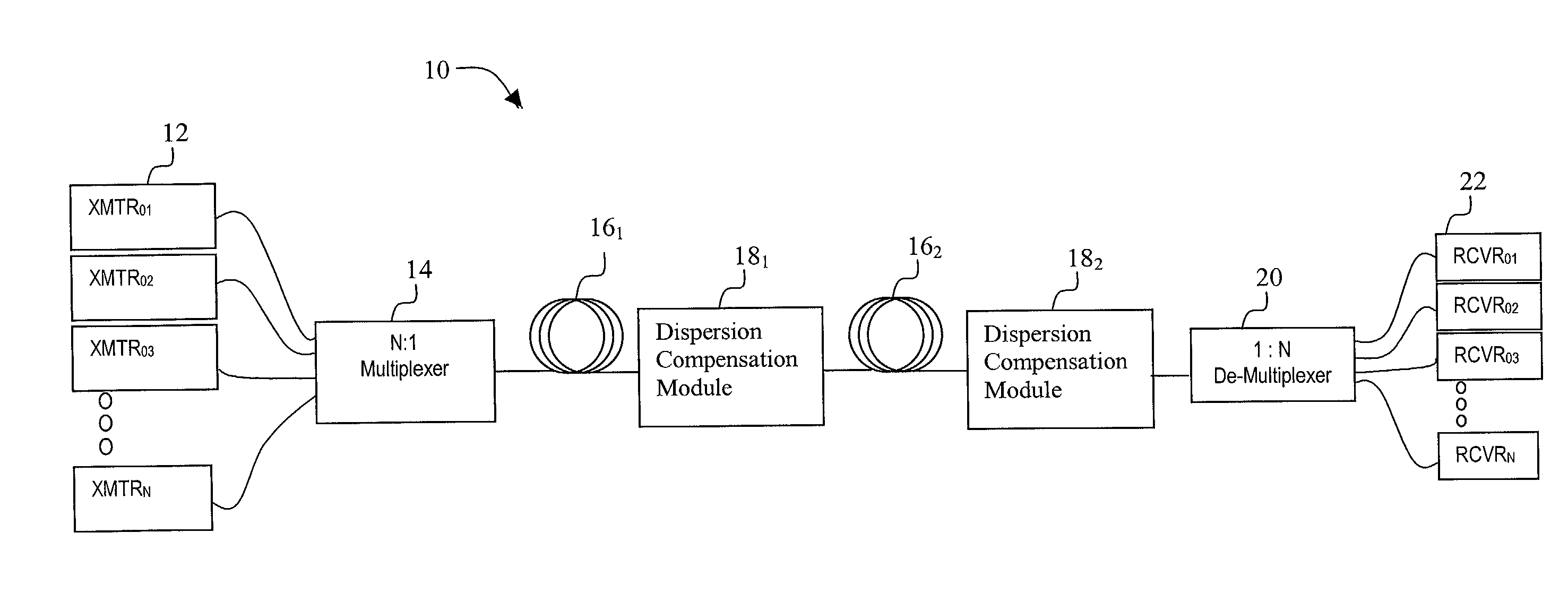
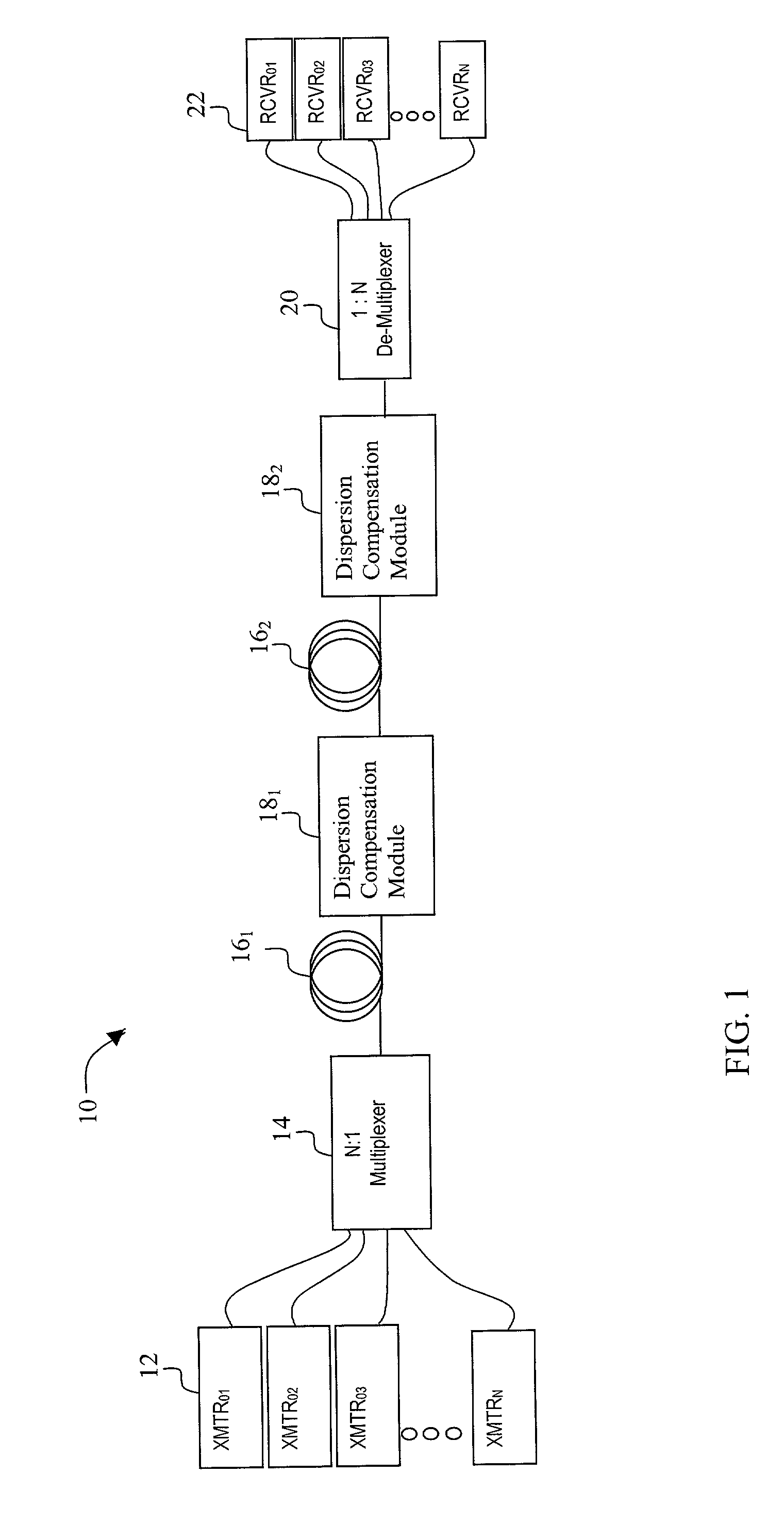
[0037] As shown in FIG. 3, sections of transmission fiber 16 are in optical communication with dispersion compensation modules 18. These sections optically connect network elements along the transmission path. Additional components such as amplifiers 50 or optical add / drop multiplexers (OADM) 52 may also be in optical communication with the transmission fiber 16 and dispersion compensation modules 18. These additional components (e.g., amplifiers, OADMs, switches, gratings, etc.) may contribute to the dispersion and dispersion slope of the transmission path between network elements and be compensated by dispersion compensation modules 18.

[0038] In the embodiment shown in FI...

second embodiment

[0042] In the invention shown in FIG. 4, lengths of DCF are selected to compensate for dispersion along the entire terminal-to-terminal path (also referred to as a span) and optionally, any associated components. As noted above, additional components such as amplifiers 50 or optical add / drop multiplexers (OADM) 52 may also be in optical communication with the transmission fiber 16 and dispersion compensation modules 18. In this embodiment, each dispersion compensation module 18 includes a single type of DCF and the lengths of DCF are selected based on the solution to equations (4) and (5) for the entire span or terminal-to-terminal transmission path. At least two dispersion compensation modules 18 employ DCF having different dispersion slopes.

[0043] As shown in FIG. 4, dispersion compensation module 18.sub.1 includes DCF 42 and dispersion compensation module 18.sub.2 includes DCF 44, having a dispersion coefficient and / or a dispersion slope coefficient different than those of DCF 42...


PUM


Abstract

An exemplary embodiment of the invention is an optical communications network transmitting signals on multiple wavelengths. The network includes a first dispersion compensating fiber providing dispersion compensation and dispersion slope compensation. The first dispersion compensating fiber has a first non-zero dispersion coefficient and a first non-zero dispersion slope coefficient. The network also includes a second dispersion compensating fiber in optical communication with the first dispersion compensating fiber. The second dispersion compensating fiber has a second non-zero dispersion coefficient and a second non-zero dispersion slope coefficient. The lengths of first dispersion compensating fiber and second dispersion compensating fiber are selected to compensate dispersion and compensate dispersion slope in a transmission path in optical communication with the first dispersion compensating fiber and the second dispersion compensating fiber. The compensation of dispersion and dispersion slope in the transmission fiber path occurs simultaneously for multiple wavelengths. Alternate embodiments include a method of compensating dispersion in an optical communications network.

Description

[0001] 1. Field of Invention[0002] The invention relates generally to a method and system for providing dispersion and dispersion slope compensation.[0003] 2. Description of Related Art[0004] Dispersion is a known phenomenon in optical networks that causes a broadening of input pulses as they travel along the length of the fiber. One type of dispersion relevant to the invention is chromatic dispersion (also referred to as "material dispersion" or "intramodal dispersion"), caused by a differential delay of various wavelengths of light in a waveguide material.[0005] Dispersion has a limiting effect on the ability to transmit high data rates. When modulated onto an optical carrier, an optical spectrum is broadened in linear proportion to the bit rate. The interaction of the broadened optical spectrum with wavelength-dependent group velocity (i.e., dispersion) in the fiber introduces signal distortions. The amount of tolerable distortion is inversely proportional to the bit rate. Thus, ...

Claims


Application Information

Patent Timeline
IPC IPC(8): G02B6/34H04B10/18
CPCH04B10/2525G02B6/29394
Inventor FRIES, TIMOTHYSARDESAI, HARSHAD
Owner CIENA
Why Eureka
Try Eureka