
Optical transmission tube and applications thereof

a technology of optical transmission tube and optical transmission tube, applied in the direction of lighting applications, instruments, roads, etc., can solve the problems of insufficient or insufficient light distribution, uneven or insufficient initial cost or operation, and inefficient energy consumption

Inactive Publication Date: 2002-10-31
BRIDGESTONE CORP
View PDF18 Cites 288 Cited by
  • Summary
  • Abstract
  • Description
  • Claims
  • Application Information

AI Technical Summary

Benefits of technology

[0014] An advantage of the invention is the ability to provide directional light in a manner that minimizes energy use or energy loss in the form of heat from the light source, because a directional optical transmission tube is used.

Problems solved by technology

Previously in the art, such illumination has either (1) not been accomplished at all due to prohibitive cost, engineering impossibility, bulkiness, undesirable design such as excessive heat buildup, or the like, or (2) has been accomplished using a variety of solutions that are inefficient, expensive in initial cost or to operate, uneven or insufficient in light distribution, energy inefficient, dangerously hot in operation, bulky or large in dimension for the application or space available, or the like.
These bulbs included no more than marginal light directional control, were generally of insufficient focus or directionality, did not evenly illuminate an entire area, and illuminated in undesirable warm or hot temperatures.

Method used


Image

  • Optical transmission tube and applications thereof
  • Optical transmission tube and applications thereof
  • Optical transmission tube and applications thereof

Examples


Embodiment Construction

[0080] Referring now to the drawings and the following exemplary descriptions of the present invention, there is shown and described illustrative embodiments of the invention. It is appreciated that these drawings and description are not limiting, and that the present invention can be used in other applications and can be realized in different embodiments.

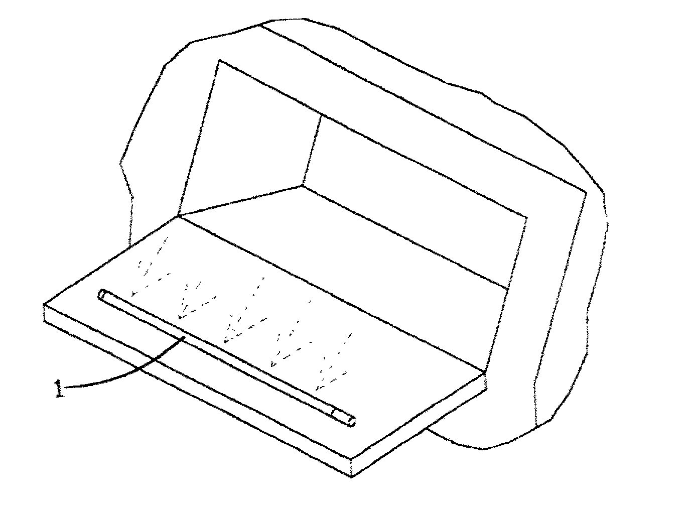
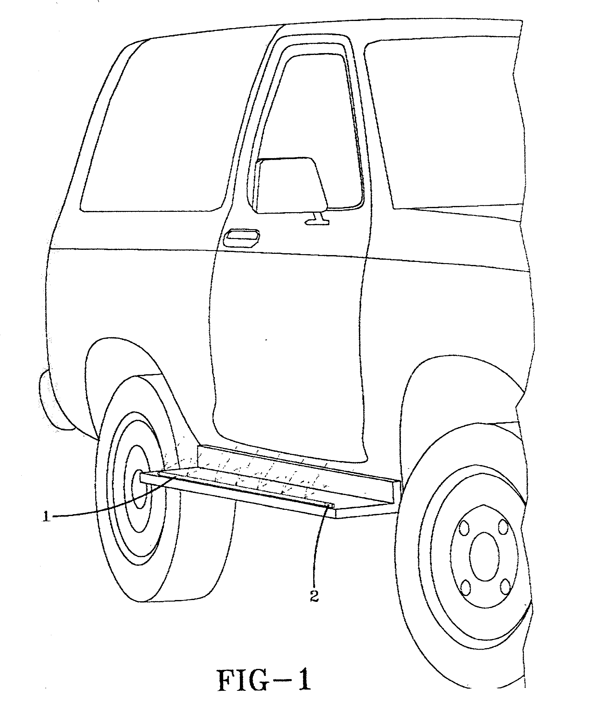
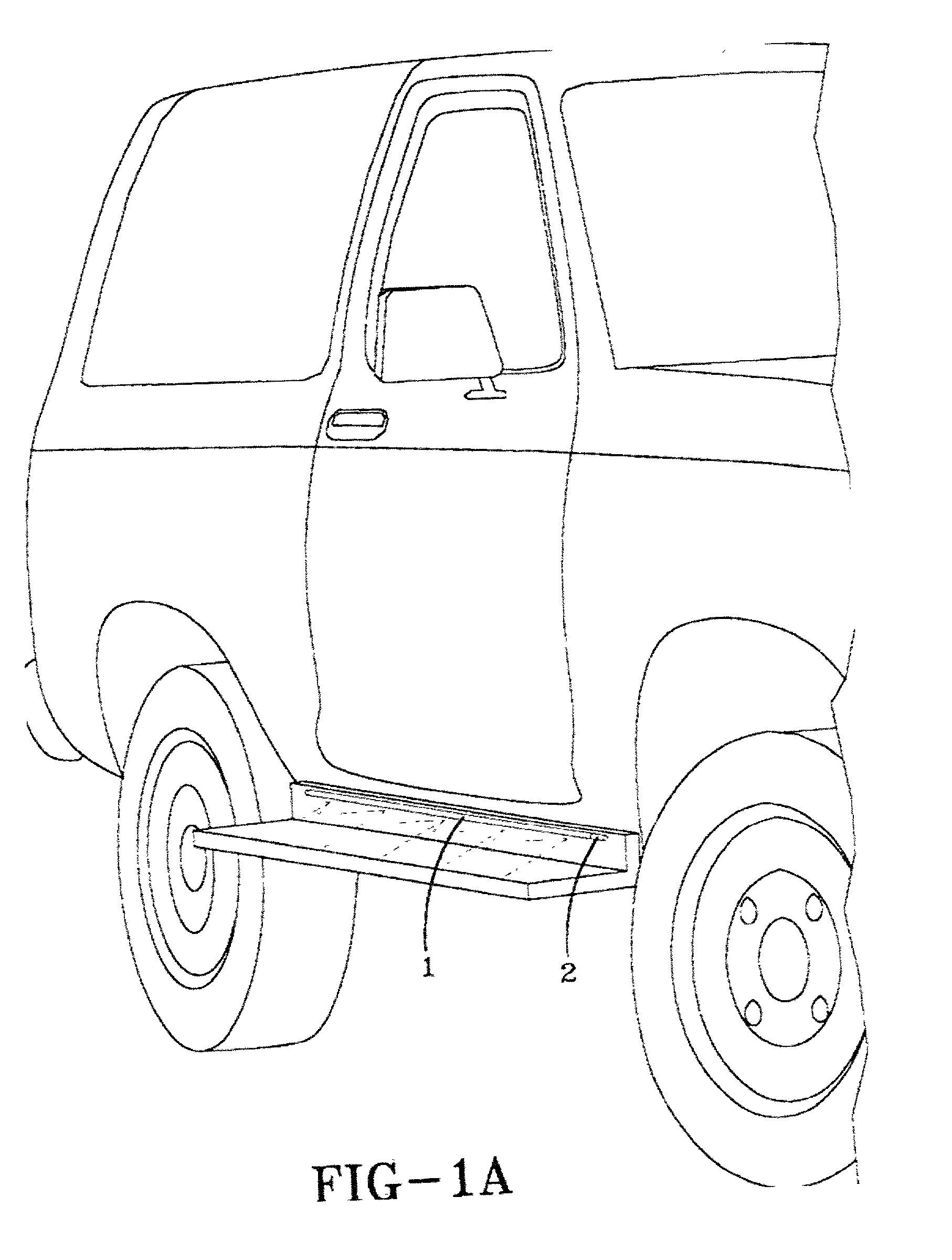
[0081] Generally, the invention is an optical transmission tube 1 incorporated into any one of a variety of automotive, commercial, retail, structural, architectural, safety, or other products. The optical transmission tube 1 includes a tubular transparent body capable of allowing light to be transmitted substantially along its entirety from a light source 2 positioned approximate to the end of the tube. The tube 1 can be affixed to provide illumination to a structure, a feature thereof such as an edge or face, a compartment therein, an area therearound or thereunder, or to accent or backlight the structure or features thereon.

[008...


PUM


Abstract

An optical transmission tube for illumination is uniquely incorporated into any one of a variety of automotive, commercial, retail, structural, architectural, safety, or other products including running boards, vehicle interior compartments such as a glove box, approximate the license plate attachment area on a vehicle, a trunk, a vehicle hood, on a vehicle door, a vehicle bumper, a vehicle luggage rack, a picture frame, a flashlight, a building, a guard rail, a construction barrier, a bicycle, a sign, an appliance interior compartment such as a refrigerator, a part bin, a retail display shelf, a clipboard, a step, a tractor trailer, a desk, a walkway, a room or storage chamber, a runway, an instrument panel, a railroad crossing gate, an emergency sign, an elevator doorway, a swimming pool, a dog collar, a fish tank, a baby crib a hand rail, an inline skate an island in a parking lot or on a street, affixed to a curb, or on safety clothing.

Description

[0001] Under 35 USC 119(e), this application claims the benefit of earlier filed provisional application NO. 60 / 271,462, filed on Feb. 26, 2001.[0002] 1. Technical Field[0003] The invention relates to devices incorporating optical transmission tube lighting systems to illuminate the area in the vicinity of the lighting system.[0004] 2. Background Information[0005] It is desirable or imperative for safety, aesthetic, security, convenience and other reasons to illuminate areas, products, devices, and the like. These include vehicles in general and the many compartments, edges or chambers thereof, and areas surrounding a structure or vehicle for safety and security purposes. These also include roads or other spaces the vehicles or other moving devices such as airplanes and boats traverse, and construction sites and the structures used in association therewith. Other examples include structures and buildings including edges, cavities, outlying regions or the like thereof. These further ...

Claims


Application Information

Patent Timeline
IPC IPC(8): B60Q1/26B60Q3/00F21V8/00
CPCB60Q1/26B60Q3/004F21W2111/023F21W2111/027F21W2111/06G02B6/001F21W2131/107F21W2131/308F21W2131/401F21Y2101/02F21Y2103/00F21W2121/06F21Y2115/10B60Q3/64
Inventor GRAVES, STEPHEN M.ISHIHARADA, MINORU
Owner BRIDGESTONE CORP
Learn More