Store for electrical energy, and holding device for at least one store for an electrically drivable vehicle

Active Publication Date: 2015-02-19
ROBERT BOSCH GMBH
View PDF8 Cites 2 Cited by
  • Summary
  • Abstract
  • Description
  • Claims
  • Application Information

AI Technical Summary

Benefits of technology

[0009]According to one refinement, the store may include a second switch which is connected to a voltage source via a resistor. The voltage source may be provided within the store or be situated externally (i.e., outside the store). One specific embodiment for the switch may be a field effect transistor, a MOSFET, for example, whose gate terminal is configured to receive a control signal. A so-called “wake-up line” is connected at a tap between the switch and the resistor, and in the case of an open switch assumes the potential of the voltage source, and in the case of a conducting second switch assumes ground potential. A control line (the gate terminal of the MOSFET, for example) is connected to the additional contact of the store, so that a predefined potential which is applied to the additional contact of the store switches on (conductively switches) the switch, and an electrical potential which is applied to the additional contact below the predefined threshold value opens the second switch. Of course, the opposite mode of operation may likewise be implemented as a function of the switch u

Problems solved by technology

However, withdrawing electrical energy from multiple stores at the same time entails the risk that so-called charge reversal processes between energy stores of different voltage or states of charge may result in very high currents which could damage the system an

Method used


Image

  • Store for electrical energy, and holding device for at least one store for an electrically drivable vehicle
  • Store for electrical energy, and holding device for at least one store for an electrically drivable vehicle
  • Store for electrical energy, and holding device for at least one store for an electrically drivable vehicle

Examples


Example

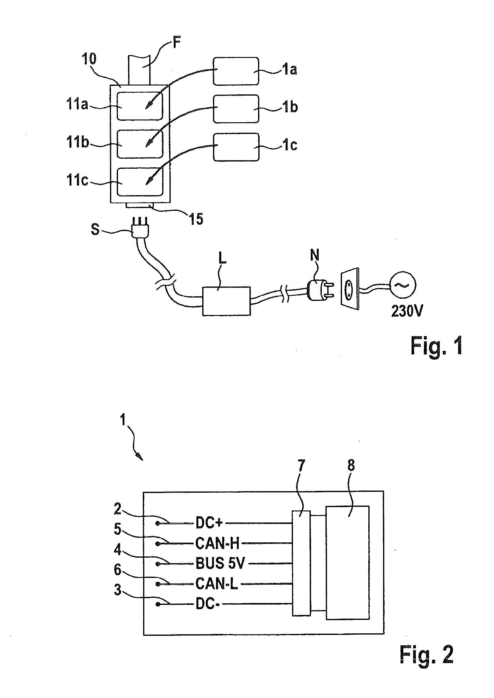
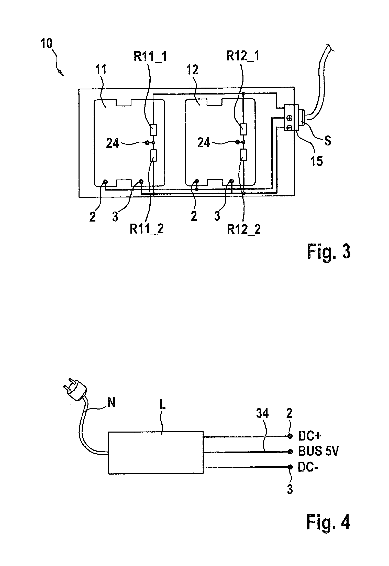
[0022]In FIG. 1, a holding device 10 is situated on a frame part of a bicycle F. Holders 11a, 11b, and 11c are configured to accommodate stores 1a, 1b, and 1c, respectively. An electrical terminal 15 is provided at the lower end of holding device 10, via which holding device 10 may be connected to a charging device L via a plug-in connector S. The charging device is configured to draw power from an electrical power supply (230 V, for example) via a power plug N. The illustrated components are discussed in greater detail below with reference to the other figures.

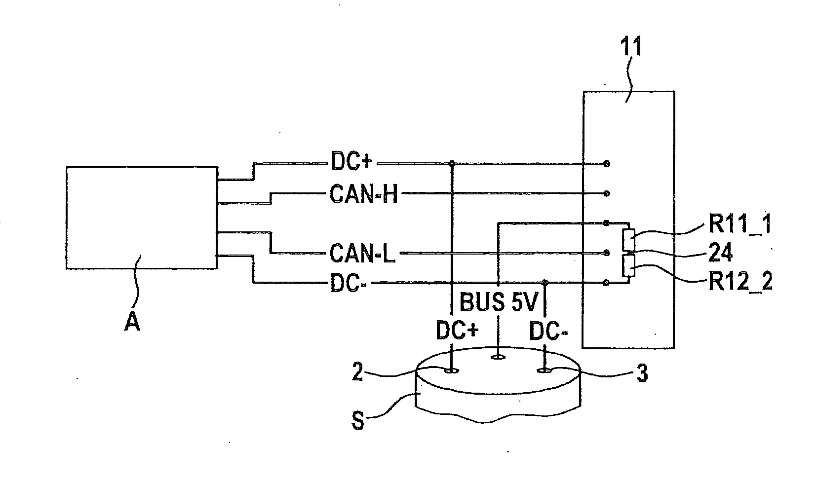
[0023]FIG. 2 shows a store 1 including five electrical terminals. A positive pole as first electrical contact 2 and a negative pole as second electrical contact 3 are provided for transmitting the electrical energy from cells 8, whereby cells 8 may be lithium-ion cells or lithium polymer cells. A so-called “CAN high” terminal (CAN-H) 5 and a “CAN low” terminal (CAN-L) 6 are provided for connecting battery management system (B...


PUM


Abstract

A store for electrical energy, and a holding device for at least two stores for electrical energy, in each of which a voltage divider is situated which is contactable in each via an external, additional electrical contact. Since the division ratio of the voltage divider within the holding device is characteristic for a specific holder, a voltage measurement at the tapping point between the stores' resistors is useable to determine which holder of the holding device the store is in. During a charging operation without the holding device no voltage divider is connected to the store, it is possible to identify a particular holder and to determine that the store is not in a holding device for charging. Since the store or its battery management system itself provides for energization of its own voltage divider, recognition may take place regardless of whether a charging device is directly connected to the holding device or store. Also, a wake-up function is provided via the additional electrical contact of the store.

Description

FIELD OF THE INVENTION[0001]The present invention relates to electrically drivable vehicles such as bicycles or automobiles.BACKGROUND INFORMATION[0002]In such vehicles, stores for electrical energy in some models may be individually introduced into the vehicle in a comparatively uncomplicated manner, for example to equip the vehicle for an imminent trip, and may subsequently be removed from the vehicle in order to be replaced by a fully charged energy store. In order to not unnecessarily increase the vehicle weight, the number of energy stores introduced into the vehicle may occasionally be adapted to the estimated travel distance. However, withdrawing electrical energy from multiple stores at the same time entails the risk that so-called charge reversal processes between energy stores of different voltage or states of charge may result in very high currents which could damage the system and / or the stores themselves. This problem exists during operation (energy withdrawal) as well ...

Claims


Application Information

Patent Timeline
IPC IPC(8): B60L11/18H02J7/00
CPCB60L11/1861B60L11/1822B60L11/1868H02J7/0068B60L3/0046B60L3/12B60L2200/12B60L2200/36B60L2240/545B60L2240/547B60L2240/549B60L2250/12B60L2250/16Y02T10/7072Y02T90/14Y04S30/14B60L53/14B60L50/20B60L53/65B60L58/19B60L58/12B60L58/21B60L58/40H02J9/005B60L58/18Y02T10/70Y02T90/12Y02T90/167Y02T10/92H02J7/0045H02J7/0048H02J2310/48Y02T90/16Y02T90/40
Inventor WALDE, NORBERTKOHLRAUSCH, PHILIPP
Owner ROBERT BOSCH GMBH
Why Eureka
Try Eureka