State projection via minimization of error energy

Active Publication Date: 2011-09-13
THE MATHWORKS INC
View PDF3 Cites 3 Cited by
  • Summary
  • Abstract
  • Description
  • Claims
  • Application Information

AI Technical Summary

Benefits of technology

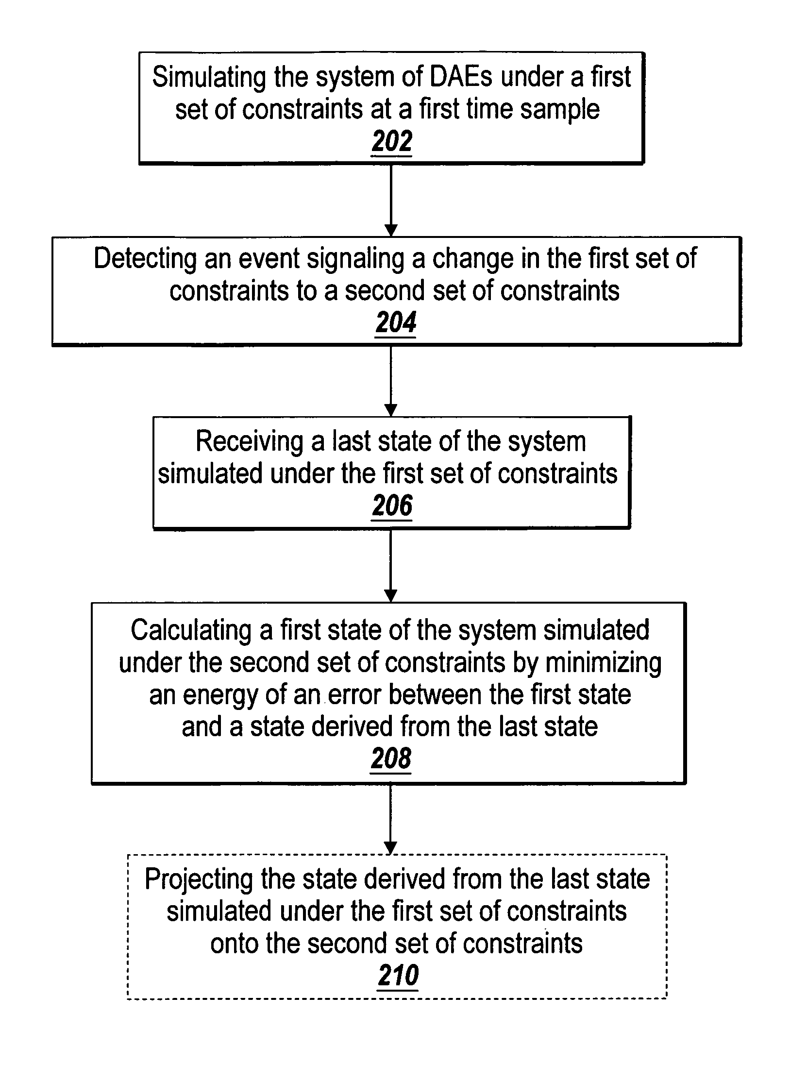
[0012]In another embodiment of the present invention, a computer-readable medium storing instructions for enabling a computing device to simulate a system of DAEs is provided. The medium includes the instructions for simulating the system of DAEs under a first set of constraints at a first time sample and detecting an event signaling a change in the first set of constraints to a second set of constraints. The medium also includes the instructions for receiving a first state of the system simulated under the first set of constraints. The medium further includes the instructions for calculating a second state of the system simulated under the second set of constraints by minimizing an energy of an error between a state derived from the first state and the second state.
[0013]In a further embodiment of the present invention, a system for simulating a system of DAEs is provided. The system includes a modeling facility including a critical event energy minimizer for minimizing an energy of an error between a state derived from a first state simulated under a first set of constraints and a second state simulated under a second set of constraints, wherein a critical event occurs that causes the modeling facility to change from simulating the system under the first set of constraints to simulating the system under the second set of constraints. The critical event may occur between two time samples. The state derived from the first state can be the same as the first state or an intermediate state derived from the first state.
[0014]In one aspect of the present invention, the first s

Problems solved by technology

Such systems range from simple to highly complex systems.
During this evolution, however, events may occur that change the set of active constraints of the system.
However, it is difficult to estimate how long (in real time) the simulation will take using the variable-step solvers.
However, because fixed-step solvers may not change the time step used within the simulation, it is very likely that the fixed-step solvers only detect the event signaling a change in constraints after the simulation has overshot th

Method used


Image

  • State projection via minimization of error energy
  • State projection via minimization of error energy
  • State projection via minimization of error energy

Examples


Example

[0025]The present invention in one aspect improves the accuracy, efficiency, and robustness of fixed-step solvers especially when simulating a physical system that does not change in energy at the critical event. The present invention may also be used with a variable-step solver as well when there is restraint in the number of time steps used or the size of the time step in the simulation. Additionally, the present invention may also be used with a system that has a change in energy at the critical event. One of ordinary skill in the art will appreciate that the present invention is not limited to the exemplary usage listed herein, and the exemplary usage should not be used to limit the scope of the present invention. In many conventional simulations, an approximation that simplifies analysis without too great a cost in accuracy is often used. Variable-step solvers are able to utilize algorithms that involve many approximations because the solvers can modify the time steps to be sma...


PUM


Abstract

The present invention improves in one aspect the accuracy, efficiency, and robustness of fixed-step solvers when simulating a physical system that does not change in energy at the critical event. The present invention uses the energy of the error as the figure of merit in finding the first state of the system under the new constraints. The present invention enables a fixed-step solver to be more robust even when the critical event falls between two time samples. The present invention may also be applied to variable-step solvers. Moreover, the present invention may also be used to simulate a physical system when the energy changes at the critical event in the physical system.

Description

TECHNICAL FIELD[0001]The present invention generally relates to computational simulation of physical systems, and more specifically to using fixed-step numerical solvers to simulate the physical systems.BACKGROUND OF THE INVENTION[0002]Various classes of graphical models describe computations that can be performed on computational hardware, such as a computer, microcontroller, field programmable gate array (FPGA), and custom hardware. Classes of such graphical models include time-based block diagrams such as those found within Simulink® from The MathWorks, Inc. of Natick, Mass., state-based and flow diagrams, such as those found within Stateflow® from The MathWorks, Inc. of Natick, Mass., entity-flow diagrams such as those found within SimEvents from The MathWorks, Inc. of Natick, Mass., data-flow diagrams, circuit diagrams, and software diagrams, such as those found in the Unified Modeling Language (UML), for example. UML is available from object management group (OMG). A common ch...

Claims


Application Information

Patent Timeline
IPC IPC(8): G06F7/60G06G7/48
CPCG06F17/5009G06F2217/16G06F30/20G06F2111/10
Inventor CHUDNOVSKY, VICTORWENDLANDT, JEFF
Owner THE MATHWORKS INC
Why Eureka
Try Eureka