Using ancillary geometry for visibility determination

Inactive Publication Date: 2002-11-07
ORACLE INT CORP
View PDF0 Cites 39 Cited by
  • Summary
  • Abstract
  • Description
  • Claims
  • Application Information

AI Technical Summary

Problems solved by technology

In addition, visualization software has shown its cost effectiveness by allowing engineering companies to find design problems early in the design cycle, thus saving them significant amounts of money.
Unfortunately, the need to view more and more complex scenes has outpaced the ability of graphics hardware systems to display them at reasonable frame rates.
As scene complexity grows, visualization software designers need to carefully use the rendering resource provided by graphic hardware pipelines.
A hardware pipeline wastes rendering bandwidth when it discards rendered triangle work.
As scene complexity increases, especially in walk-through and CAD environments, the number of occluded surfaces rises rapidly and as a result the number of surfaces that the z-buffer discards rises as well.
As depth complexity rises, the hardware pipeline thus becomes proportionally less and less effective.
Computing a scene's visibl

Method used


Image

  • Using ancillary geometry for visibility determination
  • Using ancillary geometry for visibility determination
  • Using ancillary geometry for visibility determination

Examples


Embodiment Construction

[0045] A space of any dimension may be represented as a union of cones. Convex polygonal cones may be convenient for such representations. A convex polygonal cone is a cone whose cross section is a convex polygon. A convex polygonal cone C may be expressed as the solution set of the vector inequality of the form

Sx.ltoreq.0,

[0046] where the rows of matrix S are normal vectors defining the planar boundaries of the cone C, where x is a vector variable. The vector inequality a.ltoreq.b between two vectors a and b is true if and only if a.sub.i.ltoreq.b.sub.i for all i. When S is empty, the cone C equals the entire space. When S has only one row, the cone C is a half-space. Other characterizations of a cone are possible and other embodiments based on these other characterizations are contemplated.

[0047] Most objects may be bounded by a polytope hull. A polytope hull is a convex solid whose surfaces are planar. A polytope hull H may be expressed as the solution set of the vector inequalit...


PUM


Abstract

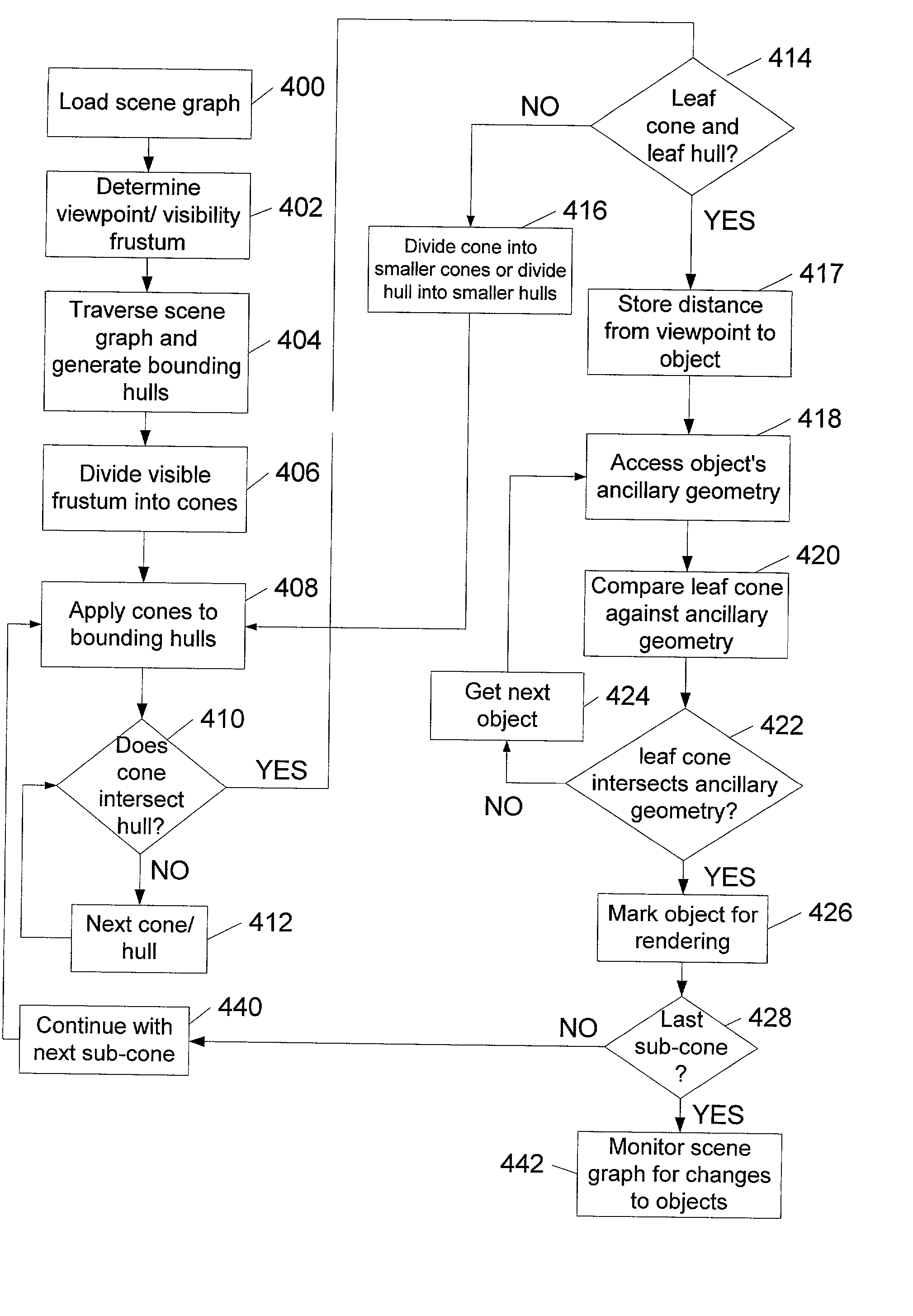
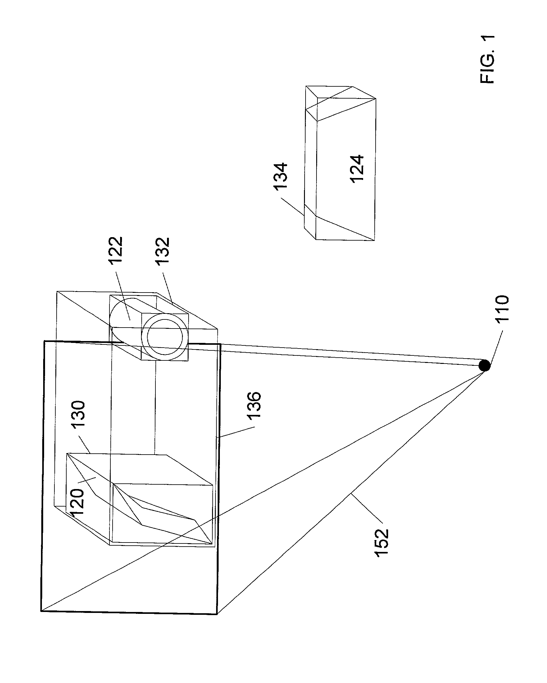
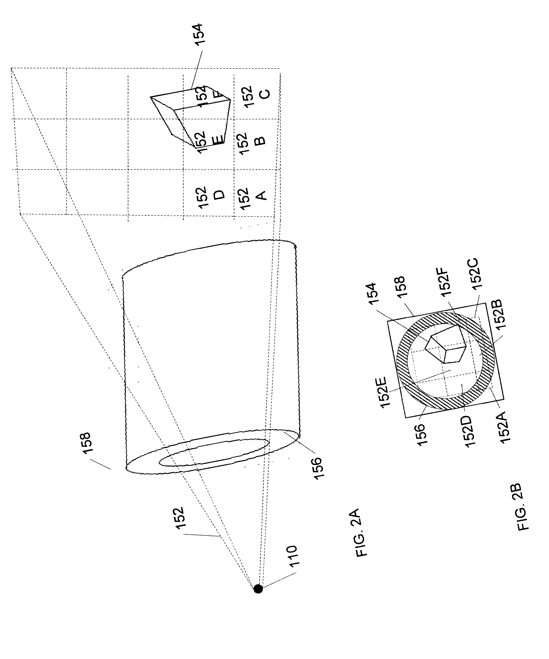
A system and method for determining graphical object visibility by utilizing ancillary geometry. When comparing visibility cones with bounding hulls of scene graph hierarchy leaf nodes, ancillary geometry may be used in place of the bounding hulls and the leaf node's actual geometry. The ancillary geometry may be created through a manual process, or by an automated decimation process. The ancillary geometry may be a simplistic analytic surface (e.g., a sphere or a cylinder), a NURB surface, a collection of polygons, or a combination of surfaces and polygons.

Description

[0001] This application claims the benefit of U.S. Provisional Application No. 60 / 254,049 filed on Dec. 6, 2000 entitled "Using Ancillary Geometry for Visibility Determination".[0002] 1. Field of the Invention[0003] The present invention generally relates to computer graphics, and more particularly, to the process of rendering three-dimensional objects.[0004] 2. Description of the Related Art[0005] Visualization software has proven to be very useful in evaluating three-dimensional designs long before the physical realization of those designs. In addition, visualization software has shown its cost effectiveness by allowing engineering companies to find design problems early in the design cycle, thus saving them significant amounts of money. Unfortunately, the need to view more and more complex scenes has outpaced the ability of graphics hardware systems to display them at reasonable frame rates. As scene complexity grows, visualization software designers need to carefully use the ren...

Claims


Application Information

Patent Timeline
IPC IPC(8): G06T15/40
CPCG06T15/40
Inventor SOWIZRAL, HENRY A.ZIKAN, KARELKELLER, RANDALL G.
Owner ORACLE INT CORP
Why Eureka
Try Eureka