Disaster recovery tape drive

a tape drive and tape drive technology, applied in the field of computer systems, can solve the problems of affecting the access to critical data, affecting the operation and environment of the system, and affecting the operation of the system,

Inactive Publication Date: 2002-11-07
HEWLETT PACKARD DEV CO LP
View PDF7 Cites 56 Cited by
  • Summary
  • Abstract
  • Description
  • Claims
  • Application Information

AI Technical Summary

Problems solved by technology

Computer systems are subject to any number of operational and environmental faults, ranging from disk failures and power outages to earthquakes and floods.
While repair or replacement of damaged equipment is costly, the interruption of access to critical data may be far more severe.
However, it also refers to more mundane events, such as data and / or applications destroyed or contaminated by equipment failures, viruses, vandalism, etc.
A server failure is especially costly, because of the potential for data loss and the crippling of the connectivity across the computer system.
A server may crash, fail to reboot, or it may recover but not function as expected.
All of these possibilities are potential consequences of a "disaster."
A company can lose most or all of its data under these situations unless a disaster recovery strategy is implemented.
Although the replacement of failed components may only take a few minutes, installing the operating system and restoring the data usually takes considerably longer.
Prolonged disaster recovery costs a business in time and revenue.
Thus, conventional disaster recovery methods are lengthy and time consuming.
The methods use several different types of media (CDs, diskettes, and tapes) to restore the server to the state it was in before the failure occurred, which increases the chances for an unsuccessful restore of the system.
For example, the media can be faulty, the diskettes or CDs not current, or parts of the disaster recovery media can be misplaced.
This and other features contribute to the costly downtime of a computing system in the event of a "disaster."

Method used


Image

  • Disaster recovery tape drive
  • Disaster recovery tape drive
  • Disaster recovery tape drive

Examples


Embodiment Construction

[0019] Illustrative embodiments of the invention are described below. In the interest of clarity, not all features of an actual implementation are described in this specification. It will of course be appreciated that in the development of any such actual embodiment, numerous implementation-specific decisions must be made to achieve the developers' specific goals, such as compliance with system-related and business-related constraints, which will vary from one implementation to another. Moreover, it will be appreciated that such a development effort might be complex and time-consuming, but would nevertheless be a routine undertaking for those of ordinary skill in the art having the benefit of this disclosure.

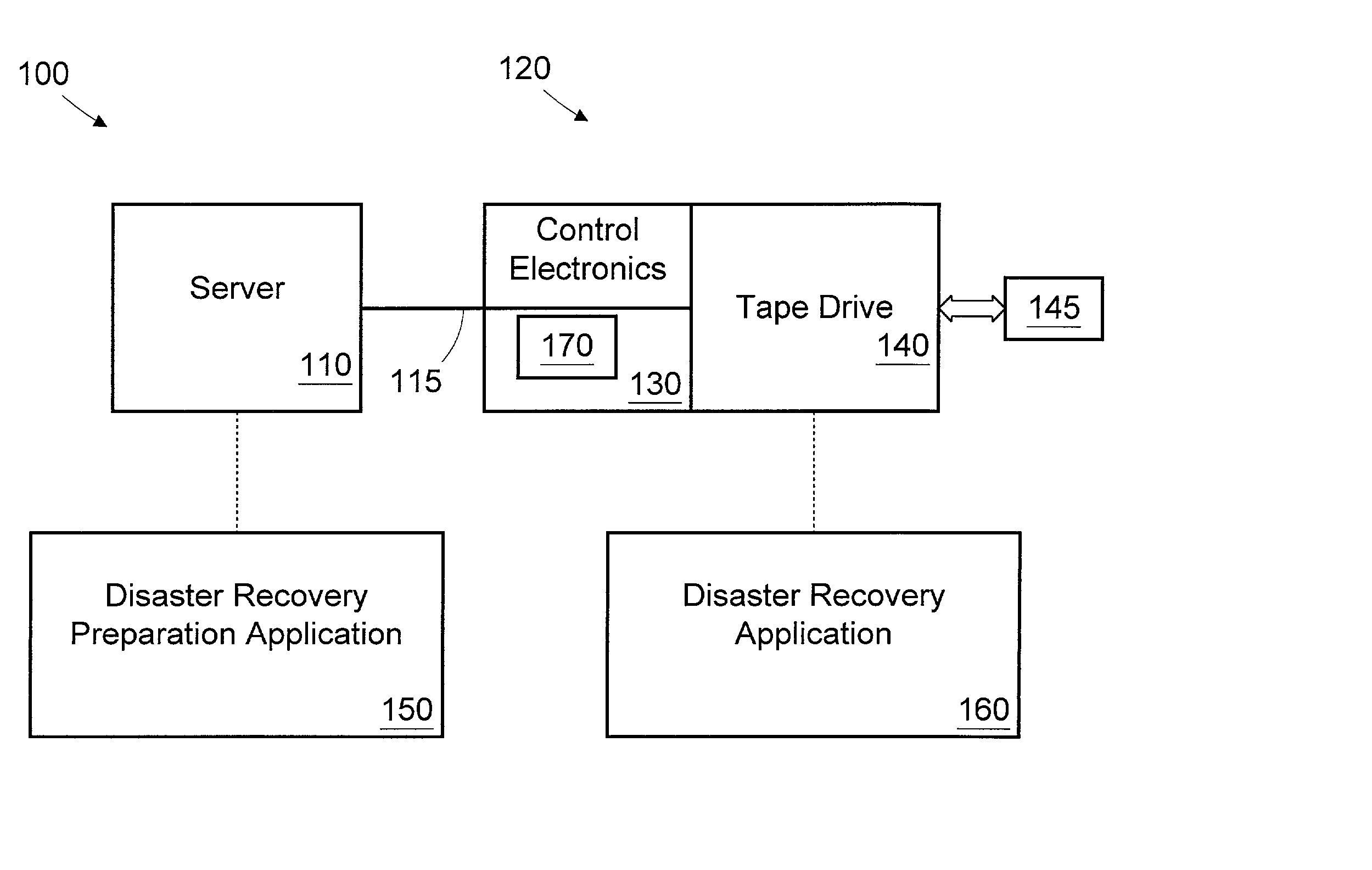
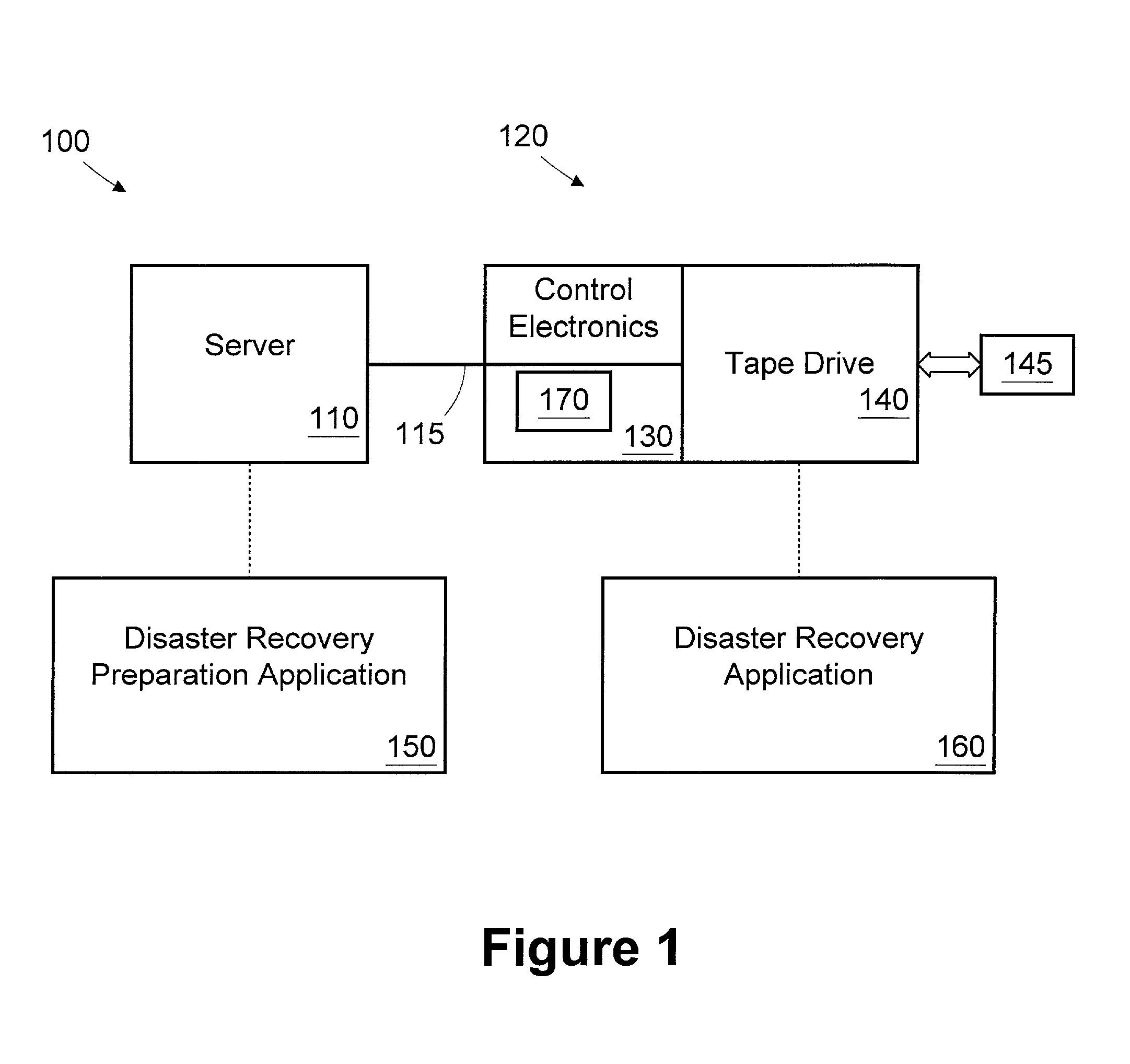
[0020] Turning now to the drawings, and first to FIG. 1, a simplified block diagram of a computer system 100 is provided. The computer system 100 includes a server 110 coupled to a tape drive assembly 120. Although this particular embodiment employs a server 110, this is not nec...


PUM

PropertyMeasurementUnit
timeaaaaaaaaaa
timeaaaaaaaaaa
timeaaaaaaaaaa

Abstract

A tape drive assembly includes a tape drive adapted to receive a tape cartridge and control electronics. The control electronics are adapted to identify whether the tape cartridge comprises a disaster recovery tape, identify a disaster recovery request, and configure the tape drive as a bootable device in response to identifying the disaster recovery request. A method for restoring a computer having a tape drive includes autonomously determining whether a tape cartridge inserted into the tape drive comprises a disaster recovery tape; identifying a disaster recovery request; and configuring the tape drive to emulate a bootable device in response to identifying the disaster recovery request.

Description

[0001] 1. Field of the Invention[0002] This invention relates generally to computer systems and, more particularly, to a bootable tape drive useful for disaster recovery.[0003] 2. Description of the Related Art[0004] Computer systems are subject to any number of operational and environmental faults, ranging from disk failures and power outages to earthquakes and floods. While repair or replacement of damaged equipment is costly, the interruption of access to critical data may be far more severe. For this reason, businesses are taking great precautions to ensure the availability of their data and their systems. In the industry, this is sometimes referred to as "disaster recovery" (i.e., the ability to restore the computer system to operational status with as little loss in data and operation as possible). The term "disaster" in this context refers to those conditions that quickly come to mind like flood, fire, earthquake, tornado, etc., and their attendant havoc. However, it also ref...

Claims


Application Information

Patent Timeline
Patent Type & Authority Applications(United States)
IPC IPC(8): G06F3/06G06F9/445G06F11/14G11B15/02G11B15/087G11B15/68
CPCG06F3/0617G06F3/0664G06F3/0682G06F8/60G11B15/689G06F11/1417G11B15/026G11B15/087G06F9/4406
Inventor LINDSEY, ALAN M.WALCZAK, KYLE A.
Owner HEWLETT PACKARD DEV CO LP
Why Eureka
Try Eureka