Method and system for performing microabrasion

a micro-abrasion and micro-abrasion technology, applied in the field of micro-abrasion systems and methods, can solve the problems of waste and unnecessary exposure to abrasive materials, preventing optimal and efficient operation on a subject or patient, and handling abrasive materials at the supply poin

Inactive Publication Date: 2002-11-14
DYNATRONICS CORP
View PDF0 Cites 23 Cited by
  • Summary
  • Abstract
  • Description
  • Claims
  • Application Information

AI Technical Summary

Problems solved by technology

Each stage of operation within current dermabrasion systems suffer problems that prevent optimal and efficient operation on a subject or patient.
One problem is the handling of the abrasive material at the supply point.
These containers are usually difficult to access and lead to waste and unnecessary exposure to the abrasive material during filling.
Further, due to the dynamics of the content level changing, the systems fail to deliver consistent amounts of abrasive material from the supply containers to the hand piece.
As such, the results of the abrasive operation are inconsistent and vary in the length of time normally needed to perform an typically procedure/session.
As the container goes from full to empty, performance can suffer severely, with as much as a 75% reduction in abrasive concentration in the air stream.
Additionally, few, if any, systems are able to utilize all the contents of the supply container before needing refilling.
An additional problem with current supply containers is that they draw upon ambient air.
Ambient air is often humid and the moisture therein causes the moisture-sensitive abrasive to agglomerate and subsequently clog the system.
This is especially a problem in that most systems utilize a small output aperture that clogs easily, particularly when the abrasive material becomes damp with humidity, leading to clumping and clogging and generally inconsistent delivery of abrasive.
Most systems lack such a control system.
Some systems utilize an electronic control that causes pulses resulting in pressure surges and non-uniform delivery of the abrasive.
Other systems utilize control systems that are difficult to adjust, hard to reset and fail to provide repeatable consistent results for subsequent treatments.
Hand pieces suffer several problems.
One problem is that the apertures tend to restrict the flow of the abrasive material to the skin as well as hinder removal of the abraded material and the abrasive during the abrasion procedure.
Further, the dermabras

Method used


Image

  • Method and system for performing microabrasion
  • Method and system for performing microabrasion
  • Method and system for performing microabrasion

Examples


Embodiment Construction

[0025] It will be readily understood that the components of the present invention, as generally described and illustrated in the figures herein, could be arranged and designed in a wide variety of different configurations. Thus, the following more detailed description of the embodiments of the system and method of the present invention, and represented in FIGS. 1 through 6, is not intended to limit the scope of the invention, as claimed, but is merely representative of the presently preferred embodiments of the invention.

[0026] The presently preferred embodiments of the invention will be best understood by reference to the drawings, wherein like parts are designated by like numerals throughout.

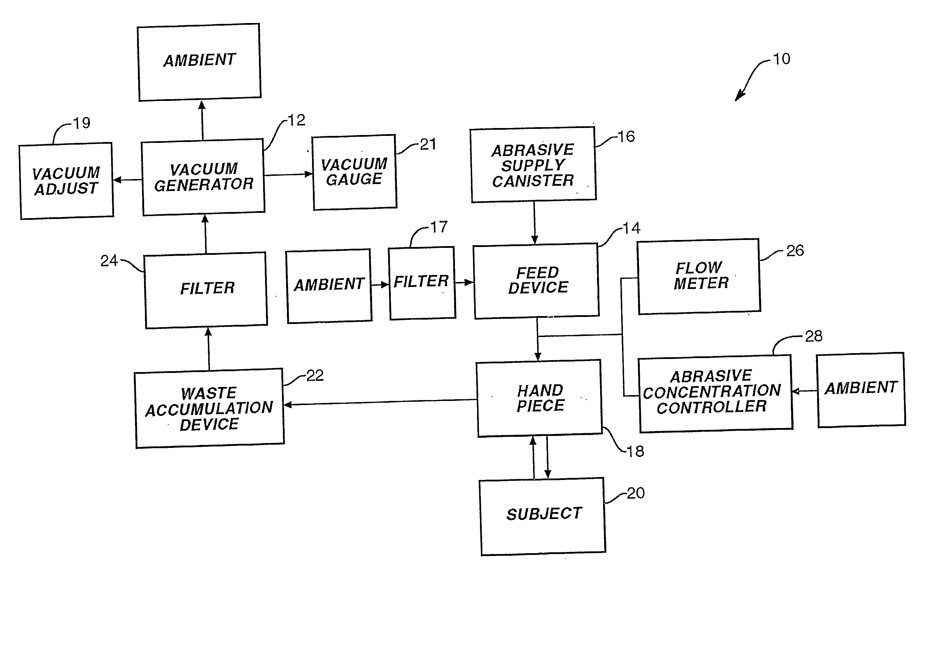
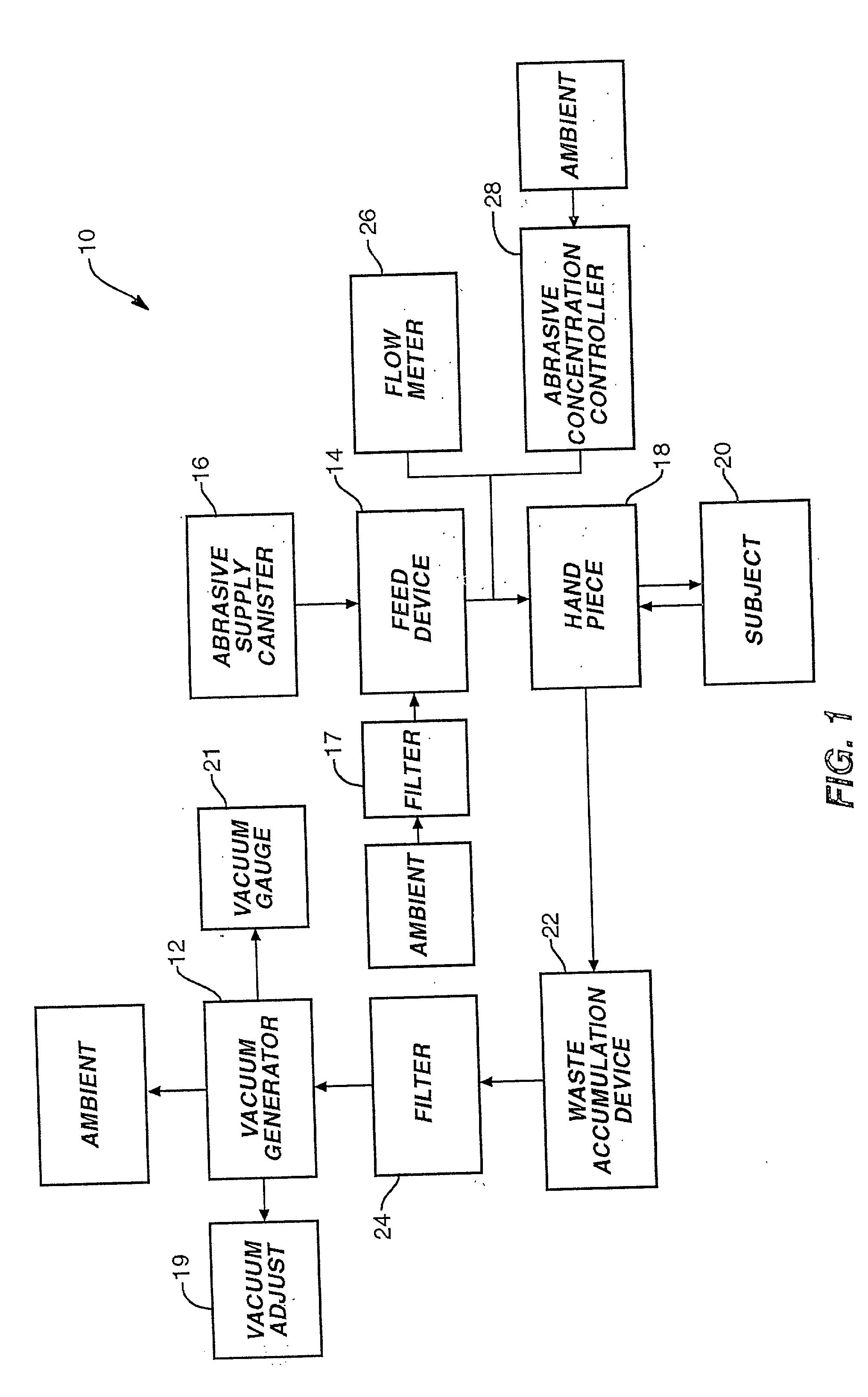
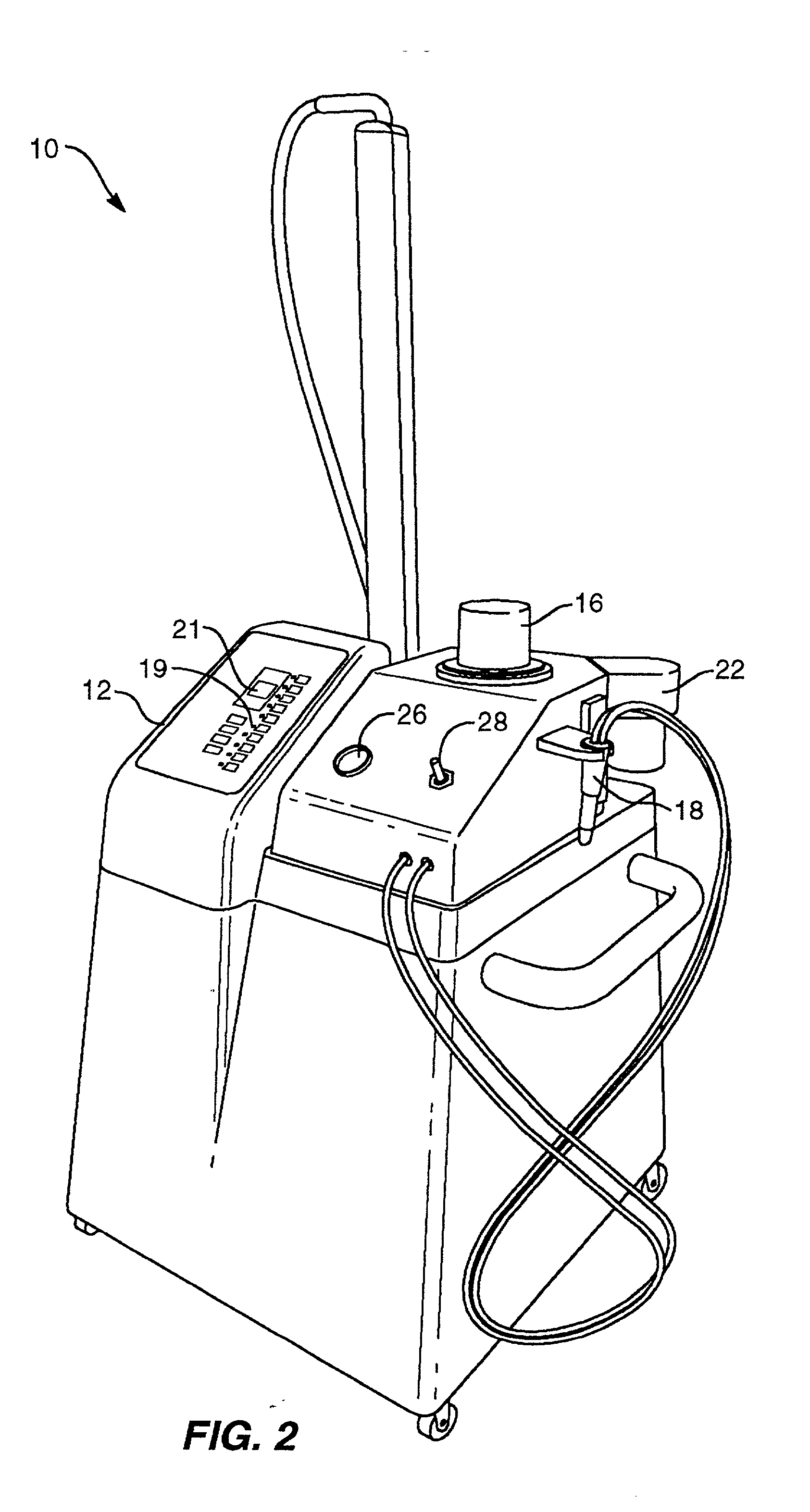
[0027] An abrasion system 10, which is optionally portable, is depicted in the block diagram of FIG. 1 as well as in FIG. 2. Dermabrasion apparatus 10 is a pneumatically driven apparatus that includes a vacuum generator 12. The pneumatic source may also be provided by a forced air system well ...


PUM


Abstract

A method and system for performing abrasion on a surface, such as on the skin of a patient, is disclosed. The dermabrasion apparatus includes means for delivering and retrieving material to and from a selected site to be abraded, a delivery and retrieval hand piece, an abrasive handling device, and a waste retrieval holding device. The hand piece is coupled to the abrasive handling device as well as the waste retrieval holding device, which is further coupled tot he delivery and retrieval means. The abrasive handling device further includes an abrasive supply device, a receiving channel, a feeding chamber, and a delivery channel. The abrasive supply device typically is a canister fitted with a funnel-shaped spout that is inverted into the receiving channel. The receiving channel feeds abrasive to the feeding chamber. The delivery and retrieval means, typically a vacuum source that generates a pneumatic air supply within the abrasion apparatus, causes the abrasive within the feeding chamber to loft in an arc such that it reaches the delivery channel. The delivery channel then leads to the hand piece, which is utilized to apply the abrasive to the surface and then retrieve the waste debris during the procedure.

Description

[0001] This patent application is related to commonly assigned U.S. Design patent application Ser. No. ______ (attorney docket No. 7536.98), entitled DERMABRASION SYSTEM, and to U.S. Design patent application Ser. No. ______ (attorney docket NO. 7536.99), entitled DERMABRASION HAND PIECE, both filed even date herewith and incorporated by reference for all purposes.THE BACKGROUND OF THE INVENTION[0002] The present invention relates generally to abrasion systems and methods for abrading a surface in a controlled manner and, more particularly, to a portable or adaptable microabrasion system that operates to perform dermabrasion in a controlled manner with improved efficiency, hygiene, and finish.[0003] Microdermabrasion techniques and systems are well known to those skilled in the art. A typical dermabrasion system includes a pneumatic drive, such as either a negative pressure system or a positive pressure system, that delivers an ablative material from a supply point to a hand piece, ...

Claims


Application Information

Patent Timeline
IPC IPC(8): A61H9/00
CPCA61H2009/0014A61H9/005
Inventor SIMON, ERIC M.BLOCK, RANDALL D.
Owner DYNATRONICS CORP
Why Eureka
Try Eureka