Method and system for performing microabrasion

a micro-abrasion and micro-abrasion technology, applied in the field of micro-abrasion systems and methods, can solve the problems of waste and unnecessary exposure to abrasive materials, preventing optimal and efficient operation on a subject or patient, and handling abrasive materials at the supply poin

Inactive Publication Date: 2003-06-24
DYNATRONICS CORP
View PDF96 Cites 96 Cited by
  • Summary
  • Abstract
  • Description
  • Claims
  • Application Information

AI Technical Summary

Benefits of technology

Further, the receiving channel extends within the feeding chamber and serves to limit or control the amount of abrasive filling the feeding chamber. The receiving chamber's height, relative to its location within the feeding chamber, can be adjusted by way of an height adjustment means. The feeding chamber typically comprises top and bottom portions as well as generally sloped side walls that slope inwardly from the top to the bottom. Such geometries lend themselves to the shapes including funnels, inverted pyramids, bowl shapes, and other geometries where the walls are sloped in such a fashion so that the abrasives accumulate in a concentrated point at the bottom. Placed between the supply device and the feeding channel is an additional chamber that provides for the abrasive to feed within the receiving channel without blocking the insertion of the funnel within the supply device. The feeding chamber is further coupled to an ambient air supply with a filter interspersed between ambient and the feeding chamber to prevent unwanted matter from being drawn within the apparatus as well as to prevent abrasive from spilling out an open aperture where the ambient port is located.

Problems solved by technology

Each stage of operation within current dermabrasion systems suffer problems that prevent optimal and efficient operation on a subject or patient.
One problem is the handling of the abrasive material at the supply point.
These containers are usually difficult to access and lead to waste and unnecessary exposure to the abrasive material during filling.
Further, due to the dynamics of the content level changing, the systems fail to deliver consistent amounts of abrasive material from the supply containers to the hand piece.
As such, the results of the abrasive operation are inconsistent and vary in the length of time normally needed to perform an typically procedure / session.
As the container goes from full to empty, performance can suffer severely, with as much as a 75% reduction in abrasive concentration in the air stream.
Additionally, few, if any, systems are able to utilize all the contents of the supply container before needing refilling.
An additional problem with current supply containers is that they draw upon ambient air.
Ambient air is often humid and the moisture therein causes the moisture-sensitive abrasive to agglomerate and subsequently clog the system.
This is especially a problem in that most systems utilize a small output aperture that clogs easily, particularly when the abrasive material becomes damp with humidity, leading to clumping and clogging and generally inconsistent delivery of abrasive.
Most systems lack such a control system.
Some systems utilize an electronic control that causes pulses resulting in pressure surges and non-uniform delivery of the abrasive.
Other systems utilize control systems that are difficult to adjust, hard to reset and fail to provide repeatable consistent results for subsequent treatments.
Hand pieces suffer several problems.
One problem is that the apertures tend to restrict the flow of the abrasive material to the skin as well as hinder removal of the abraded material and the abrasive during the abrasion procedure.
Further, the dermabrasion procedure involves removal of skin and sometimes blood, so there is concern that the use of the same wand from patient to patient is unsanitary and unhealthy.
Attempts to make the hand piece more hygienic by having disposable and replaceable wand tips has been unsuccessful as the tips merely prevent contamination at the aperture level without addressing a problem known as back contamination, which occurs when refuse debris within the wand from a previous procedure contaminates the wand tip in spite of the replacement of a fresh tip.
As such, these pieces are difficult to clean and therefore, undesirable for long term use.
Also, most hand pieces are expensive to manufacture.
They can be heavy and awkward to use, such that the technician suffers discomfort and fatigue during long sessions or over several sessions during the same day.
Since the piece needs to be small enough to handle, they often have restricted flow paths that detrimentally affect flow rate and delivery of the abrasive for optimal results and for quick pick up of the waste debris.
Most systems are permanently mounted and are difficult to access, empty, and clean.
Failure to clean the container can result in unwanted growths and other hazardous health risks that should be avoided at all times.
The waste accumulation systems often have small exhaust apertures that can easily clog with waste products resulting in restricted air flow within the overall system.
Such filters are a major source of clogging and reduction of optimal air flow within the entire system, thereby leading to poor dermabrasion results since less abrasive material is being carried within the system at a reduced speed.
Similar to the supply system, one solution has been to use back pressure to clear and clean the filters or unplug the clogs in the waste accumulation system, but this adds cost and complexity to the overall design, which can result in mechanical failure, decreased abrasion performance, and increased costs of production and operation.

Method used


Image

  • Method and system for performing microabrasion
  • Method and system for performing microabrasion
  • Method and system for performing microabrasion

Examples


Embodiment Construction

It will be readily understood that the components of the present invention, as generally described and illustrated in the figures herein, could be arranged and designed in a wide variety of different configurations. Thus, the following more detailed description of the embodiments of the system and method of the present invention, and represented in FIGS. 1 through 6, is not intended to limit the scope of the invention, as claimed, but is merely representative of the presently preferred embodiments of the invention.

The presently preferred embodiments of the invention will be best understood by reference to the drawings, wherein like parts are designated by like numerals throughout.

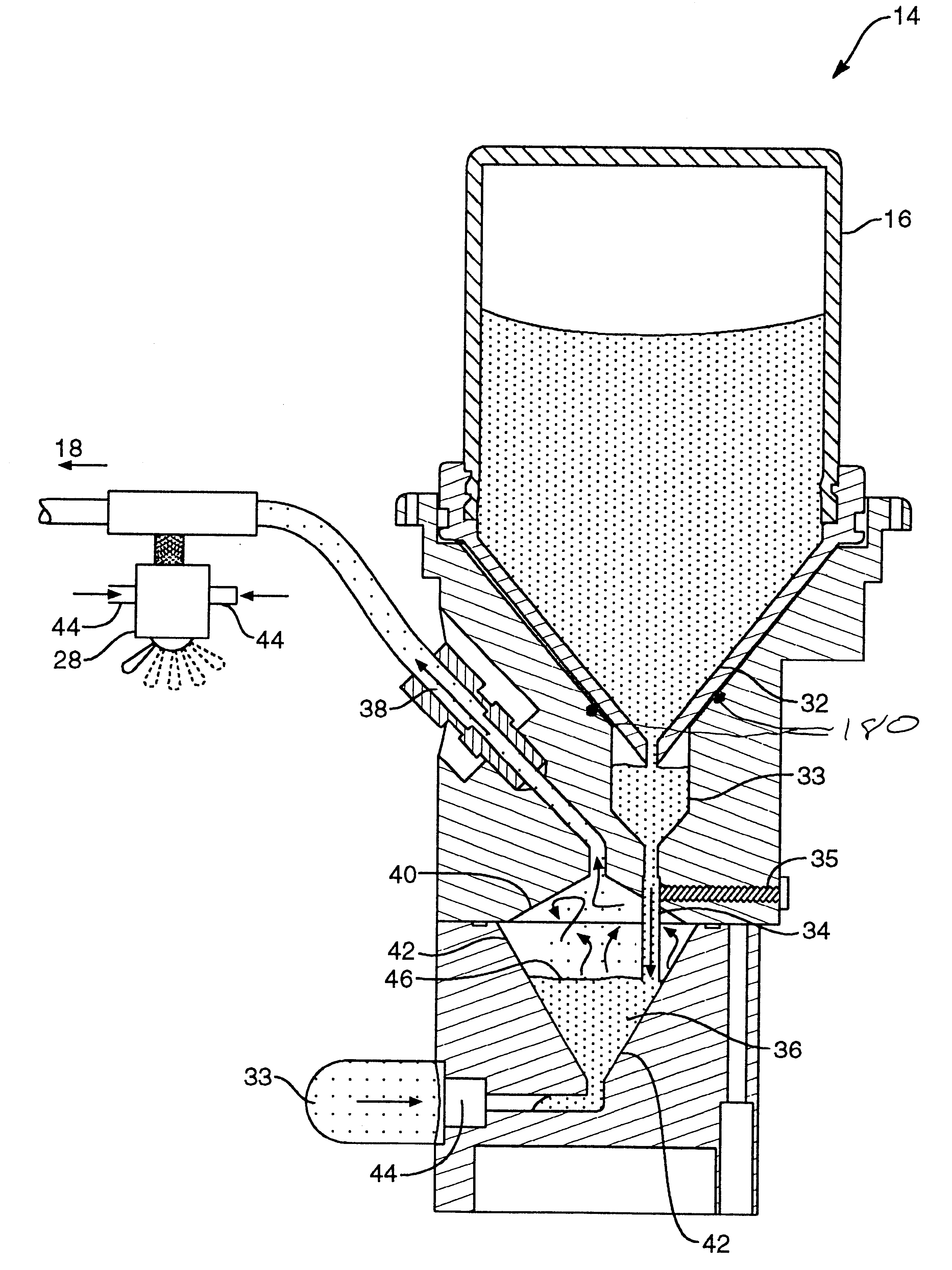
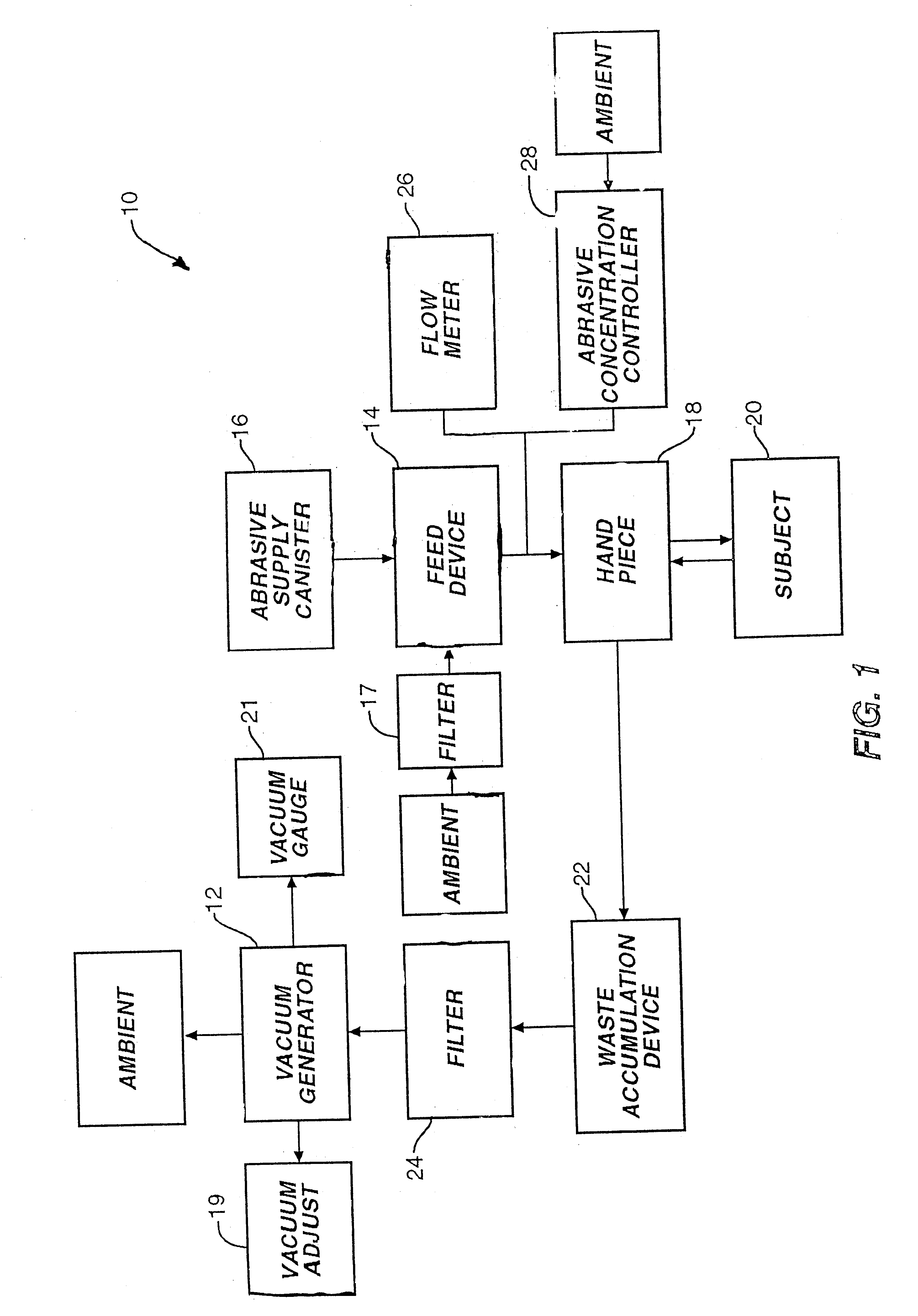
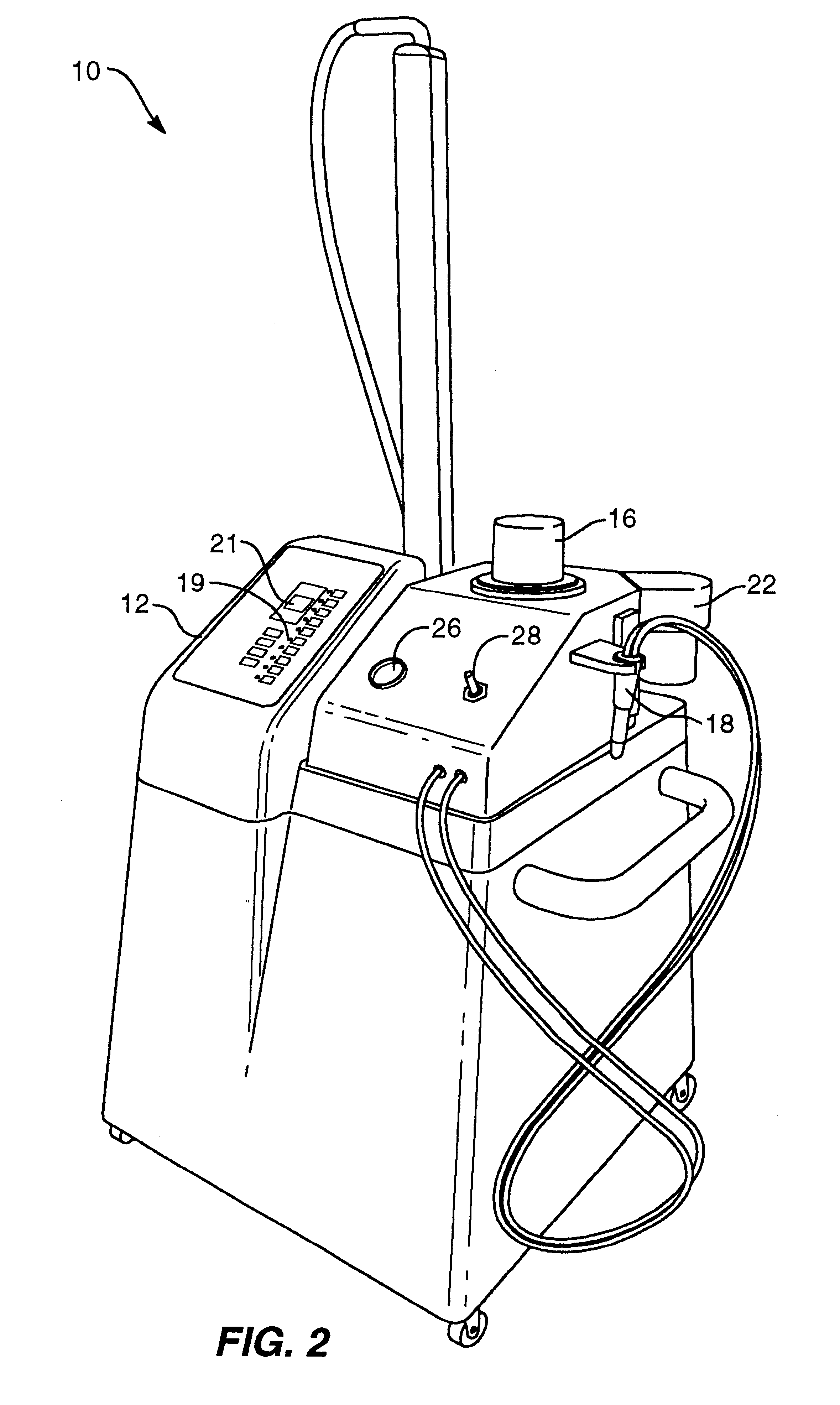
An abrasion system 10, which is optionally portable, is depicted in the block diagram of FIG. 1 as well as in FIG. 2. Dermabrasion apparatus 10 is a pneumatically driven apparatus that includes a vacuum generator 12. The pneumatic source may also be provided by a forced air system well known to those skille...


PUM


Abstract

A method and system for performing abrasion on a surface, such as on the skin of a patient, is disclosed. The dermabrasion apparatus includes apparatus for delivering and retrieving material to and from a selected site to be abraded, a delivery and retrieval hand piece, an abrasive handling device, and a waste retrieval holding device. The hand piece is coupled to the abrasive handling device as well as the waste retrieval holding device, which is further coupled to the delivery and retrieval apparatus. The abrasive handling device further includes an abrasive supply device, a receiving channel, a feeding chamber, and a delivery channel. The abrasive supply device typically is a canister fitted with a funnel-shaped spout that is inverted into the receiving channel. The receiving channel feeds abrasive to the feeding chamber. The delivery and retrieval apparatus, typically a vacuum source that generates a pneumatic air supply within the abrasion apparatus, causes the abrasive within the feeding chamber to loft in an arc such that it reaches the delivery channel. The delivery channel then leads to the hand piece, which is utilized to apply the abrasive to the surface and then retrieve the waste debris during the procedure.

Description

THE BACKGROUND OF THE INVENTIONThe present invention relates generally to abrasion systems and methods for abrading a surface in a controlled manner and, more particularly, to a portable or adaptable microabrasion system that operates to perform dermabrasion in a controlled manner with improved efficiency, hygiene, and finish.Microdermabrasion techniques and systems are well known to those skilled in the art. A typical dermabrasion system includes a pneumatic drive such as either a negative pressure system or a positive pressure system, that delivers an ablative material from a supply point to a hand piece, also known as a wand, which has a small aperture to be placed upon a patient's skin during the abrasion process. In the negative pressure system, such as one utilizing a vacuum for pneumatic drive, the closing of the aperture by the skin completes the pneumatic circuit drawing the abrasive material to the skin to perform dermabrasion. The refuse and debris after the abrasive proc...

Claims


Application Information

Patent Timeline
Patent Type & Authority Patents(United States)
IPC IPC(8): A61H9/00
CPCA61H9/005A61H2009/0014
Inventor SIMON, ERIC M.BLOCK, RANDALL D.
Owner DYNATRONICS CORP
Why Eureka
Try Eureka