1-100 GHz microstrip filter

a microstrip filter and filter body technology, applied in the field of high frequency filters, can solve the problems of high cost, large size, and need tuning after manufacturing

Inactive Publication Date: 2002-12-05
REMEC DEFENSE & SPACE INC
View PDF5 Cites 9 Cited by
  • Summary
  • Abstract
  • Description
  • Claims
  • Application Information

AI Technical Summary

Problems solved by technology

Drawbacks of these waveguide and dielectric resonator filters is that they are relatively expensive, require tuning after manufacturing and are bulky in size.

Method used


Image

  • 1-100 GHz microstrip filter
  • 1-100 GHz microstrip filter
  • 1-100 GHz microstrip filter

Examples


Embodiment Construction

[0016] The numerous innovative teachings of the present application will be described with particular reference to the presently preferred exemplary embodiments. However, it should be understood that this class of embodiments provides only a few examples of the many advantageous uses of the innovative teachings herein. In general, statements made in the specification of the present application do not necessarily delimit any of the various claimed inventions. Moreover, some statements may apply to some inventive features but not to others.

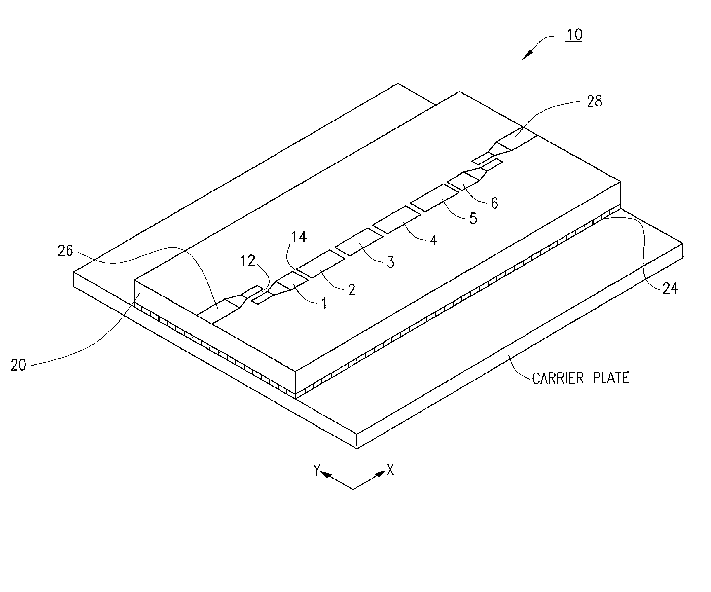
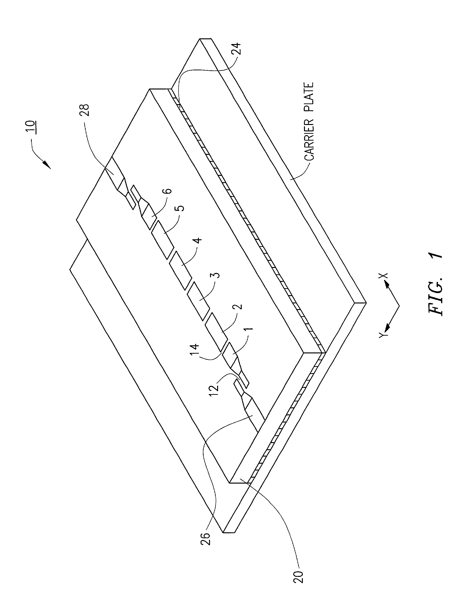
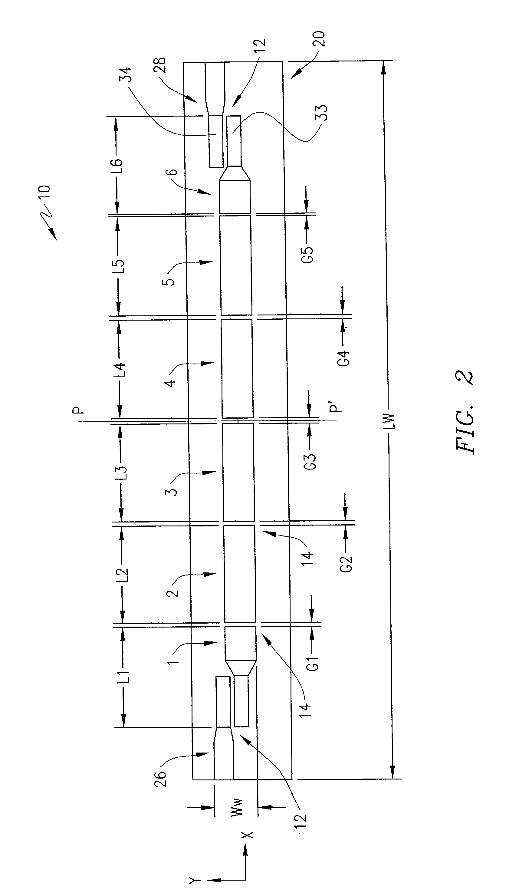
[0017] Microstrip filters occupy a smaller volume than waveguide cavity filters and dielectric resonator filters. Generally, microstrip filters use well known printed circuit techniques for their fabrication. Microstrip filters are inexpensive to manufacture and easily reproducible. Prior microstrip filters utilized a single type of coupling between resonators. For example the filter may only utilize transverse couplings or only utilize longitudinal...


PUM


Abstract

A high frequency filter design for the GHz frequency range is provided. The high frequency filter comprises at least a microstrip design that incorporates both transverse and lateral couplings between the filters resonators. The high frequency filter further incorporates an opened or fully enclosed enclosure over the strip line or microstrip circuitry and may be manufactured on a relatively thick dielectric substrate having a thickness that is greater than about a twentieth of the filter's band-pass wavelength in the dielectric substrate. The high frequency filter design provides a small, easily reproducible filter design better than prior art microstrip filters.

Description

[0001] 1. Technical Field of the Invention The present invention relates generally to high frequency filters. More specifically, the present invention relates to high frequency filters in the 1 GHz to 100 GHz range that utilize patterned resonators formed on a dielectric substrate.[0002] 2. Description of Related Art[0003] High frequency filters, such as low-pass, high-pass, band-pass, and notch filters, are very important components of modern communication systems. In particular, wireless, mobile, and optical communication systems utilize band-pass filters for isolating particular frequency channels. The frequency channels presently of interest are in a range of between 1 GHz and 100 GHz. Band-pass filters allow signals in a certain frequency band (in band frequencies) to be transmitted through the band-pass filter with minimal attenuation. The band-pass filter strongly attenuates other undesired frequencies (out of band frequencies). In the range of frequencies extending from abou...

Claims


Application Information

Patent Timeline
Patent Type & Authority Applications(United States)
IPC IPC(8): H01P1/203
CPCH01P1/20381H01P1/20363
Inventor MONGIA, RAJESH
Owner REMEC DEFENSE & SPACE INC
Why Eureka
Try Eureka