Phase-change optical disk and optical disk apparatus

Inactive Publication Date: 2002-12-05
SONY CORP
View PDF1 Cites 41 Cited by
  • Summary
  • Abstract
  • Description
  • Claims
  • Application Information

AI Technical Summary

Problems solved by technology

It is thus impossible to correctly read the data from the recording area.
This may cause a problem in detecting a synchronization mark when reading data.
Specifically, if a known optical disk apparatus cannot detect a sync byte functioning as a data sync prior to a data area in a recording area in a sector

Method used


Image

  • Phase-change optical disk and optical disk apparatus
  • Phase-change optical disk and optical disk apparatus
  • Phase-change optical disk and optical disk apparatus

Examples


first embodiment

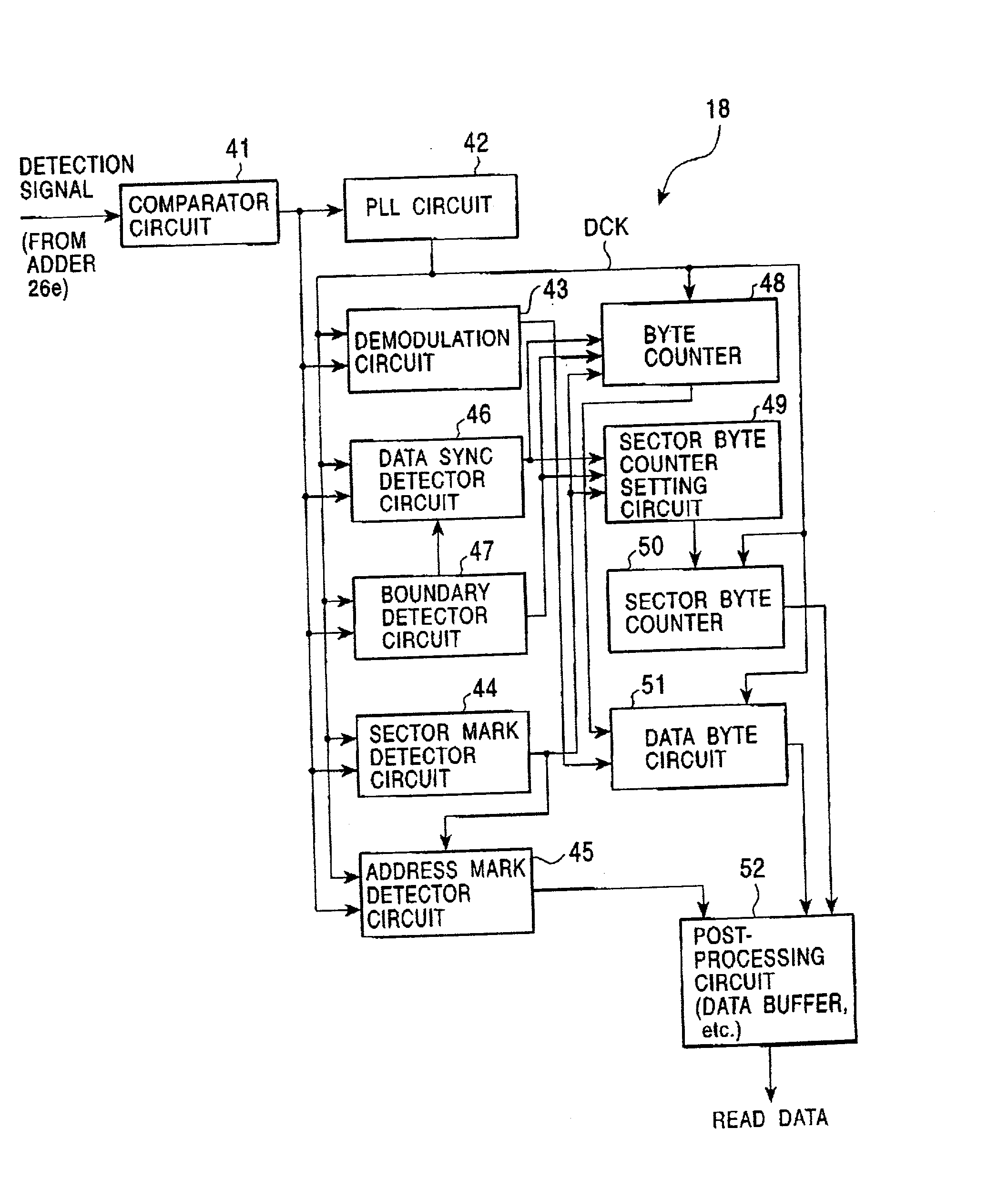
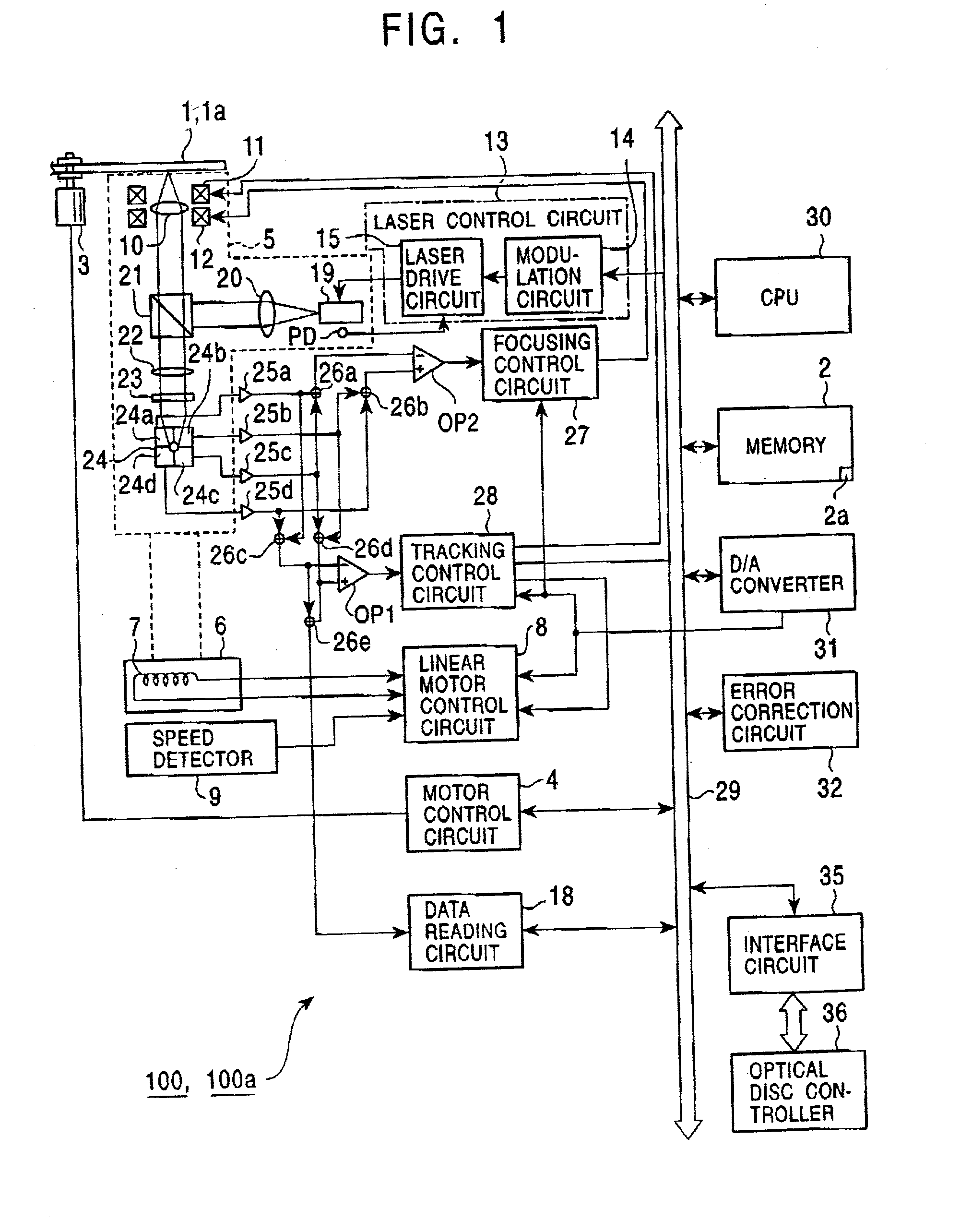
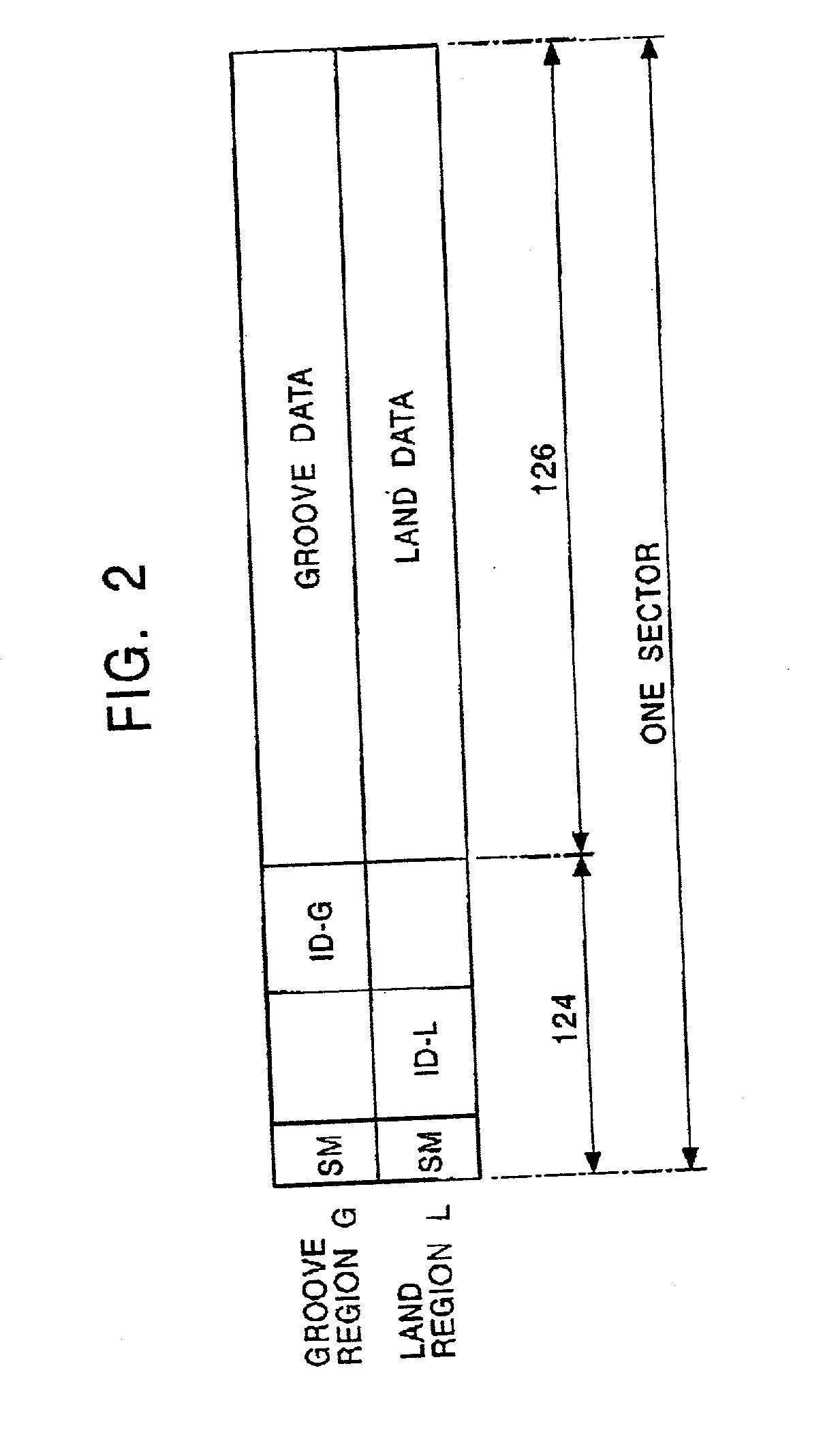
[0041] FIG. 1 shows the configuration of an example of an optical disk apparatus 100 according to the present invention. FIG. 2 illustrates an example of a sector format of an optical disk 1 shown in FIG. 1.

[0042] The optical disk apparatus 100 has a function for writing data to, for example, the phase-change optical disk 1 using condensed light or a function for reading recorded data. The optical disk 1 is manufactured by coating the surface of a disk-shaped substrate formed of glass or plastic with a metal-coated layer, such as layer coated with tellurium or bismuth, in the shape of a donut.

[0043] In the phase-change recording system, the metal-coated layer formed in the Interior of the optical disk 1 is irradiated with a laser beam. At a high temperature of approximately 600.degree. C., the metal-coated layer changes to an amorphous (non-crystal)-molecular state in which the molecules are not organized. At approximately 400.degree. C., the molecular state of the metal-coated laye...

second embodiment

[0109] Since an optical disk apparatus 100a and an optical disk la of a second embodiment are substantially the same as those of the first embodiment, which are shown in FIGS. 1 to 6, the same reference numerals as those shown in FIGS. 1 to 6 are given to the same components, and repetitive descriptions of common portions are omitted. Mainly, portions that are different are described.

[0110] FIG. 7 is a timing chart showing an example of a random shift. FIG. 8 is an enlarged view of the synchronous code VFO and the like shown in FIG. 7. FIG. 9 illustrates an example in which the detection window 61 is placed at the boundary K between the synchronous code VFO and the pre sync PreSync and the boundary K is thus detected.

[0111] The optical disk 1 according to the second embodiment differs from the optical disk 1 according to the first embodiment, shown in FIGS. 4 to 6, in that the pre sync PreSync is divided into, for example, eight small 10-byte regions T1 to T8, as shown in FIGS. 7 to...


PUM


Abstract

An optical disk apparatus for a phase-change optical disk detects the boundary between a first region and a second region prior to detecting a synchronization mark. The synchronization mark is detected in accordance with the position of the detected boundary between the first region and the second region. User data is read from a data region in accordance with the detected synchronization mark.

Description

[0001] 1. Field of the Invention[0002] The present invention relates to phase-change recording-system optical disks (hereinafter referred to as phase-change optical disks) and optical disk apparatuses for reading user data in accordance with a synchronization mark recorded in a recording region by using a random shift.[0003] 2. Description of the Related Art[0004] In phase-change optical disks, a mark is recorded by making a laser-spot-section amorphous. In order to prevent deterioration of a medium due to repetitive recording, that is, in order to increase the number of times a recording film can be overwritten, the start position for writing data is randomly shifted. This technology is referred to as "random shift".[0005] In known phase-change optical disks, only a few bytes are prepared for a sync byte as a data sync, which is provided to acquire byte synchronization when reading data, after a gap preceding a recording area in which data is written using a random shift. When the ...

Claims


Application Information

Patent Timeline
IPC IPC(8): G11B20/14G11B7/0045G11B7/005G11B7/007
CPCG11B7/00454G11B7/007G11B7/0051
Inventor NAGATA, MASAYOSHICHIBA, TAKAYOSHITONE, YASUOYAMAGUCHI, SHIGEOHORIGOME, JUNICHI
Owner SONY CORP
Why Eureka
Try Eureka