Seal structure of a fuel cell

Inactive Publication Date: 2002-12-12
TOYOTA JIDOSHA KK
View PDF9 Cites 45 Cited by
  • Summary
  • Abstract
  • Description
  • Claims
  • Application Information

AI Technical Summary

Benefits of technology

[0012] Another object of the present invention is to provide a seal structure of a fuel cell capable of preventing a sealant from being bulged out from between seal surfaces as well as assuring a uniform seal pressure.

Problems solved by technology

First, it is difficult to assure a uniform seal. Since a thickness of the sealant differs by a thickness of the electrolyte membrane between at a region where an electrolyte membrane exists and at another region where the electrolyte membrane does not exist, a seal pressure imposed on the sealant changes and a uniform seal pressure is not assured. More particularly, at the region where the electrolyte membrane exists a large pressure acts on the sealant and the creep of the sealant is large so that the seal pressure decreases with the lapse of time, which is accompanied by loosening of the tightening force of the stack and thereby decreasing the output the fuel cell.
Second, not only is there the above seal pressure variance due to whether the electrolyte membrane exists or not between the seal surfaces, but there also is a variance in the coated thickness of the sealant which makes it difficult to obtain a uniform seal pressure. At a place where an over-pressure acts on the sealant, the sealant may be bulged out from between the seal surfaces. If the bulged sealant decreases a cross-sectional area of a gas passage or blocks the gas passage, the output of the fuel cell will be badly affected.

Method used


Image

  • Seal structure of a fuel cell
  • Seal structure of a fuel cell
  • Seal structure of a fuel cell

Examples


first embodiment

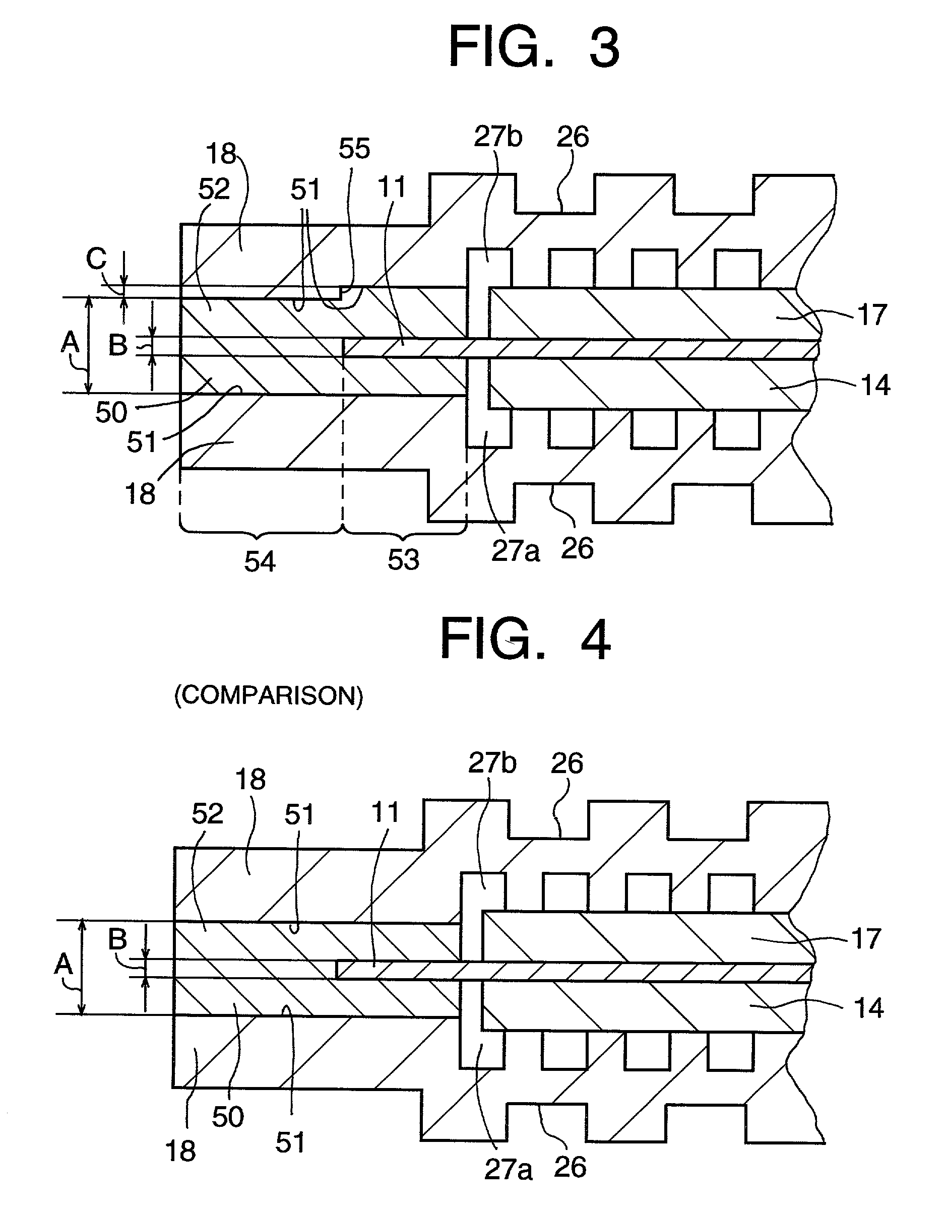
[0047] With the present invention, as illustrated in FIG.3, a first distance (A+C) between the first and second seal surfaces 51 at a first region 53 where the electrolyte membrane 11 exists between the first and second seal surfaces 51 and a second distance (A) between the first and second seal surfaces 51 at a second region 54 where the electrolyte membrane 11 does not exist between the first and second seal surfaces 51 differ from each other so that a first surface portion located at the first region 53 of at least one of the first and second seal surfaces 51 recedes from a remaining, second surface portion located at the second region 54 of the at least one of the first and second seal surfaces 51. The sealant collecting structure is constructed of the first surface portion.

[0048] The first distance (A+C) is greater than the second distance (A) by a thickness (B) of the electrolyte membrane 11, where (C) is equal to (B). As a result, a thickness (A) of the sealant at the first r...

second embodiment

[0054] With the second embodiment of the present invention, as illustrated in FIG. 5, a concave 56 is formed in at least one of the first and second seal surfaces 51 of the first and second separators 18 opposing each other via the electrolyte membrane 11. The sealant collecting structure is constructed of the concave 56 in the second embodiment of the present invention. The concave 56 can be a groove, a recess, or chamfer. A cross-section of the concave 56 can be rectangular, triangular, polygonal, semi-circle, R-shaped, or of a chamfer.

[0055] The at least one of the first and second seal,surfaces 51 has a width and includes an inner portion (a portion closer to the electrode) and an outer portion (a portion further from the electrode) in the width, and the concave 56 may be formed (a) in the inner portion of the seal surface 51 of the separator 18, (b) in an outer portion of the seal surface 51 of the separator 18, or (c) both in the inner portion and the outer portion of the seal...

third embodiment

[0062] With the third embodiment of the present invention, as illustrated in FIG. 6, the first and second separators 18 have sizes different from each other in the direction perpendicular to the fuel cell stacking direction, and the sealant collecting structure includes a space 57 formed outside a side surface of a smaller-sized separator. More particularly, a larger-sized separator extends further than the smaller-sized separator by 3-5 mm, and the space 57 is formed above an upper surface of the larger-sized separator and outside the side surface of the smaller-sized separator.

[0063] FIGS. 9 and 10 illustrate comparisons which are not included in the present invention. If the opposing separators have the same sizes, when the sealant is bulged out to a side surface of the module, the bulged sealant drops and adheres to the side surface of the module. It is necessary to remove the sealant from the side surface of the module by a cutter knife or other devices. If the sealant is bulge...


PUM


Abstract

A seal structure of a fuel cell includes a first seal surface formed in a first separator disposed on one side of an electrolyte membrane and a second seal surface formed in a second separator disposed on the other side of the electrolyte membrane, and a sealant collecting structure formed in or outside at least one of the first and second seal surfaces. The sealant collecting structure is constructed of a stepped receding surface formed in at least one of the first and second seal surfaces, a concave or groove formed in an inner portion and / or an outer portion of at least one of the first and second seal surfaces, a space formed outside at least one of the separators, or a stepped recess formed in at least one of the separators. The sealant collecting structure receives an extra sealant therein to ensure uniform seal pressure acting on the sealant and to prevent the extra sealant from being bulged out to gas passages and to a gas manifold.

Description

[0001] 1. Field of the Invention[0002] The present invention relates to a seal structure of a fuel cell of a polymer electrolyte-type.[0003] 2. Description of Related Art[0004] A PEFC (Polymer Electrolyte Fuel Cell) apparatus includes individual fuel cells. Each fuel cell includes a membrane-electrode assembly (MEA) and a separator. The MEA includes an electrolyte membrane and a pair of electrodes disposed on opposite sides of the electrolyte membrane. The pair of electrodes includes an anode provided on one side of the membrane and constructed of a first catalyst layer and a cathode provided on the other side of the membrane and constructed of a second catalyst layer. A first diffusion layer may be provided between the first catalyst layer and a first separator and a second diffusion layer may be provided between the second catalyst layer and a second separator. The first separator has a passage formed therein for supplying fuel gas (hydrogen) to the anode and the second separator ...

Claims


Application Information

Patent Timeline
IPC IPC(8): H01M8/02H01M8/10
CPCH01M8/0271Y02E60/50H01M8/0297H01M8/0276H01M8/0258H01M8/0267H01M8/241H01M8/2457
Inventor KATO, CHISATOKIYOKAWA, YOSHIOAKIYAMA, SHIRO
Owner TOYOTA JIDOSHA KK
Why Eureka
Try Eureka