Manufacturing method of airtight container and image displaying apparatus

Inactive Publication Date: 2010-07-29
CANON KK
View PDF11 Cites 9 Cited by
  • Summary
  • Abstract
  • Description
  • Claims
  • Application Information

AI Technical Summary

Benefits of technology

[0009]The present invention aims, in a manufacturing method of an airtight container including a process of sealing a through-hole by a cover member, to provide the manufacturing method which can secure sealing performance and also restrain a sealant from flowing into the through-hole. Moreover, the present invention aims to provide a manufacturing method of an image displaying apparatus, which uses the relevant manufacturing method of the airtight container.
[0013]According to the present invention, in the airtight container manufacturing method including sealing the through-hole by the cover member, it is possible to provide the airtight container manufacturing method which can efficiently secure the sealing performance and also restrain the sealant from flowing into the through-hole. Moreover, according to the present invention, it is possible to provide the image displaying apparatus manufacturing method which uses the airtight container manufacturing method described as above.

Problems solved by technology

This is because, although it is necessary to heat and then soften or melt the sealant to uniformly arrange and form it around the through-hole, there is a fear at this time that the sealant flows into the through-hole due to a difference between internal and external pressures of the container.
Thus, since the cap is in tightly contact with the through-hole easily, it becomes difficult for the sealant to flow into the through-hole.
More specifically, although most sealant flows into the tapered portion, there is a possibility that a part of the sealant flows into the through-hole due to the vacuum inside the container.
For this reason, since it is difficult in the patent document 2 to uniformly distribute the sealant, there is a possibility that it is difficult to obtain sufficient sealing performance.

Method used


Image

  • Manufacturing method of airtight container and image displaying apparatus
  • Manufacturing method of airtight container and image displaying apparatus
  • Manufacturing method of airtight container and image displaying apparatus

Examples


first embodiment

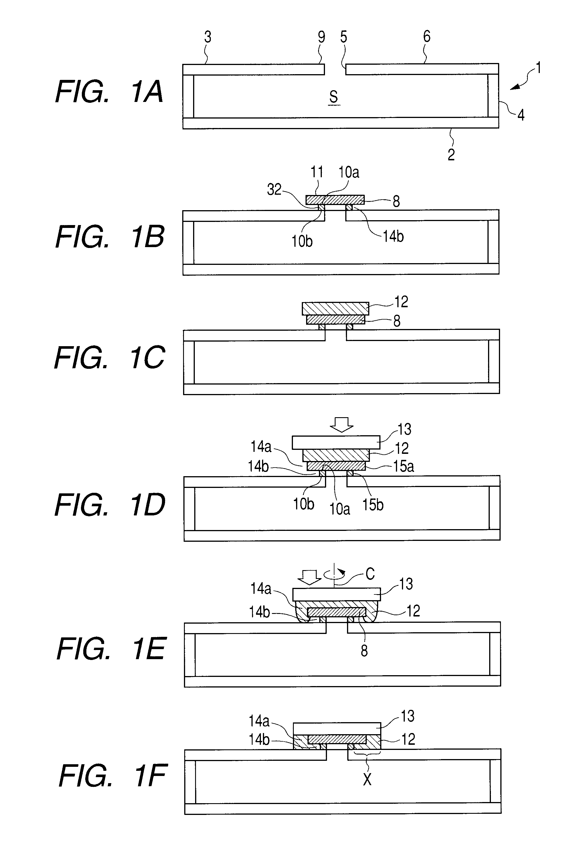
[0023]The first embodiment of the present invention will be described with reference to FIGS. 1A to 1F. Here, FIGS. 1A to 1F are the schematic step views indicating a sealing process, which can be particularly preferably used in a case where a through-hole is sealed under a state that the through-hole of an airtight container is placed on the upper surface of an envelope.

[0024](Step S1)

[0025]Initially, an inside S of a container 1 is exhausted via a through-hole 5 provided on the surface of the container 1. The container 1 can have desired materials and constitution. In case of a flat panel image displaying apparatus, a part of the container 1 is usually manufactured by glass. In the present embodiment, as indicated in FIG. 1A, the container 1 is composed of a face plate 2, a rear plate 3 and a support frame 4, which are mutually bonded by a proper means such as a glass frit or the like, to form an airtight container. A large number of electron emitters (not illustrated) for emittin...

second embodiment

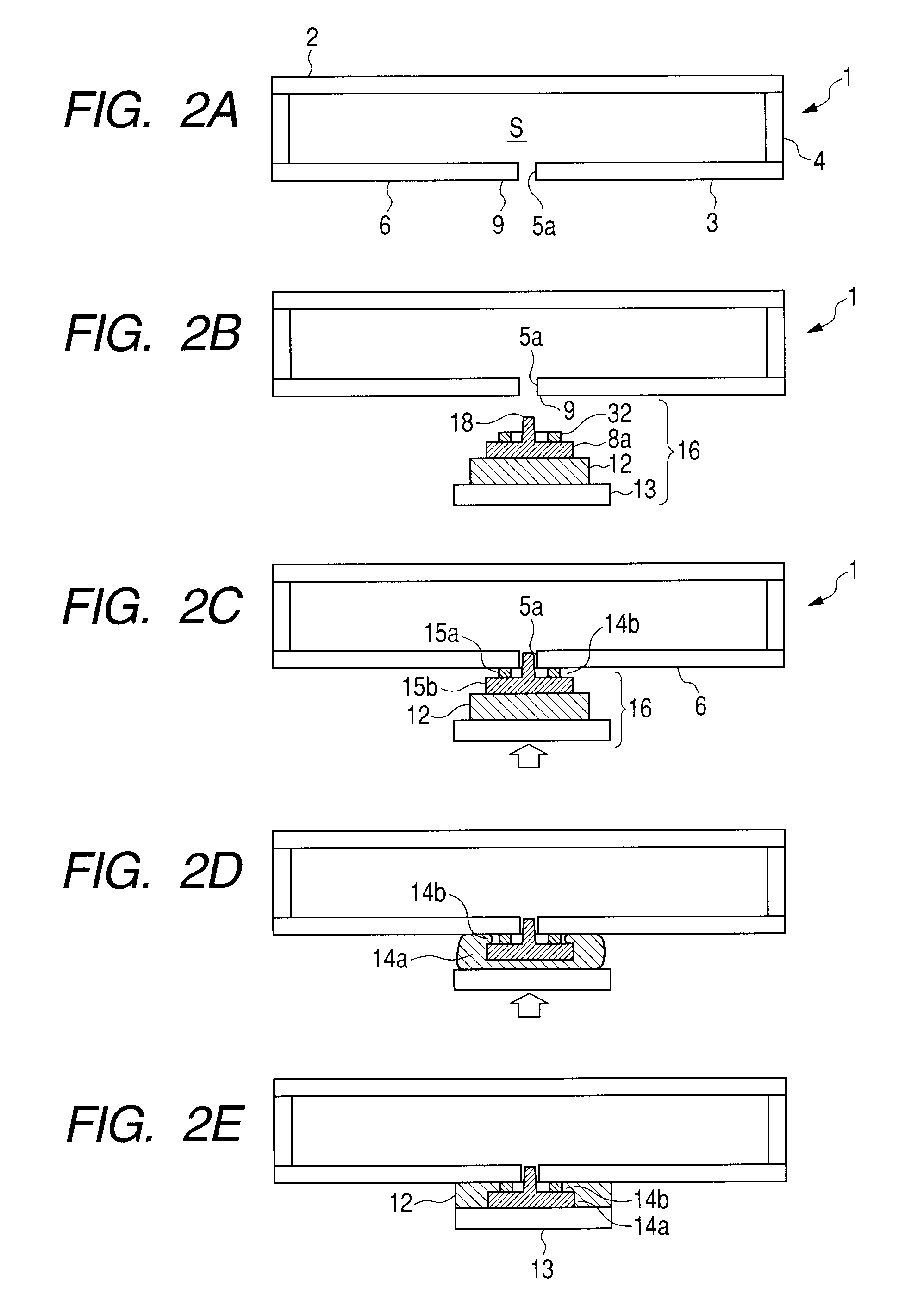
[0040]The present embodiment is different from the first embodiment in a point that the through-hole is sealed by bringing a laminated body composed of the spacer member, the plate member, the sealant and the cover member into contact with the through-hole from the downside of the through-hole, and other points in the present embodiment are the same as those in the first embodiment. Therefore, in the following description, the point different from the first embodiment will be mainly described. Namely, as to the matters not described in the following, the description in the first embodiment should be referred.

[0041]The second embodiment of the present invention will be described with reference to FIGS. 2A to 2E. FIGS. 2A to 2E are the schematic step views indicating a sealing process which can be especially preferably used in a case where the through-hole is sealed in a state that the through-hole of the airtight container was opened to the vertical downward direction.

[0042](Step S51...

example 1

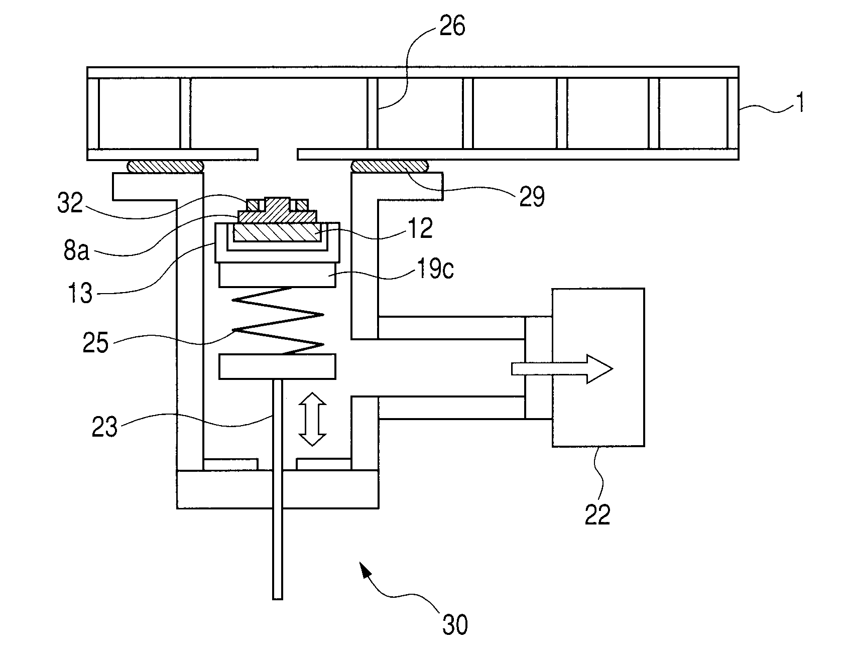
[0054]This is an example of manufacturing an airtight container by using the first embodiment illustrated in FIG. 1. Hereinafter, this example will be described with reference to FIG. 3.

[0055]In this example, the container 1 was stored in a vacuum-exhaust chamber 31, and the vacuum-exhaust chamber 31 was then exhausted to be vacuumized by using an exhaust unit 22 containing a turbo molecular pump and a dry scroll pump. Further, heaters 19a and 19b used as heating units were provided in the vacuum-exhaust chamber 31, and the through-hole 5 having the diameter of 3 mm was provided on the upper surface of the container 1.

[0056]As the plate member 8, a soda lime glass having the diameter of 5 mm and the thickness of 300 μm was prepared. As the sealant 12, a glass frit, which was molded to have the diameter of 7 mm and the thickness of 400 μm by pre-baking and from which a paste component had been eliminated, was prepared. As the cover member 13, a soda lime glass having the diameter of ...


PUM

PropertyMeasurementUnit
Diameteraaaaaaaaaa
Electrical conductoraaaaaaaaaa
Areaaaaaaaaaaa

Abstract

In airtight container manufacturing method including sealing a through-hole by a cover, it secures sealing performance and restrains sealant from flowing into the through-hole. The method comprises: (a) exhausting inside of a container through the through-hole; (b) arranging a spacer along periphery of the through-hole on an outer surface of the container the inside of which has been exhausted; (c) arranging a plate so that the spacer and the through-hole are covered by the plate and gap is formed along a side surface of the spacer between the plate and the container outer surface; and (d) arranging the cover to cover the plate and bonding the cover and the container outer surface via sealant positioned between the cover and the container outer surface, wherein the sealing includes hardening the sealant after deforming the sealant as pressing the plate by the cover so that the gap is infilled with the sealant.

Description

BACKGROUND OF THE INVENTION[0001]1. Field of the Invention[0002]The present invention relates to a manufacturing method of an airtight container. In particular, the present invention relates to a manufacturing method of a vacuum airtight container (envelope) used for a flat panel image displaying apparatus.[0003]2. Description of the Related Art[0004]An image displaying apparatus, in which a number of electron-emitting devices for emitting electrons according to image signals are provided on a rear plate and a fluorescent film for displaying an image by emitting light in response to irradiation of electrons is provided on a face plate, and of which the inside is maintained with vacuum, has been known. In the image displaying apparatus like this, generally, the face plate and the rear plate are bonded to each other through a support frame, thereby forming an envelope. In case of manufacturing the image displaying apparatus like this, it is necessary to exhaust the inside of the envel...

Claims


Application Information

Patent Timeline
IPC IPC(8): B65B31/00
CPCH01J9/261H01J9/40H01J29/86H01J2209/26Y10T29/49147Y10T29/49146Y10T29/49826Y10T29/49915
Inventor NAKAZAWA, TOMONORIKAMIGUCHI, KINYAKAWASE, TOSHIMITSUITO, NOBUHIROHASEGAWA, MITSUTOSHINAKANISHI, KOICHIROKOYANAGI, KAZUO
Owner CANON KK
Why Eureka
Try Eureka