
Vertically and horizontally adjustable chair armrest

Inactive Publication Date: 2002-12-19
HNI TECH INC
View PDF0 Cites 23 Cited by
  • Summary
  • Abstract
  • Description
  • Claims
  • Application Information

AI Technical Summary

Benefits of technology

[0007] There are a number of advantages, features and objects achieved with the present invention which are believed not to be available in earlier related devices. For example, one advantage is that the present invention provides an armrest assembly that is easily adjustable both vertically and horizontally. Another object of the present invention is to provide an adjustable chair armrest that is simply constructed and reliable. Yet another advantage of the present invention is an armrest assembly that is easy to form and then easy to assemble.
[0008] A more complete understanding of the present invention and other objects, advantages and features thereof will gained from a consideration of the following description of a preferred embodiment read in conjunction with the accompanying drawing provided herein. The preferred embodiment represents an example of the invention which is described here in compliance with Title 35 U.S.C. section 112, but the invention itself is defined by the attached claims.BRIEF DESCRIPTION OF THE SEVERAL VIEWS OF THE DRAWING
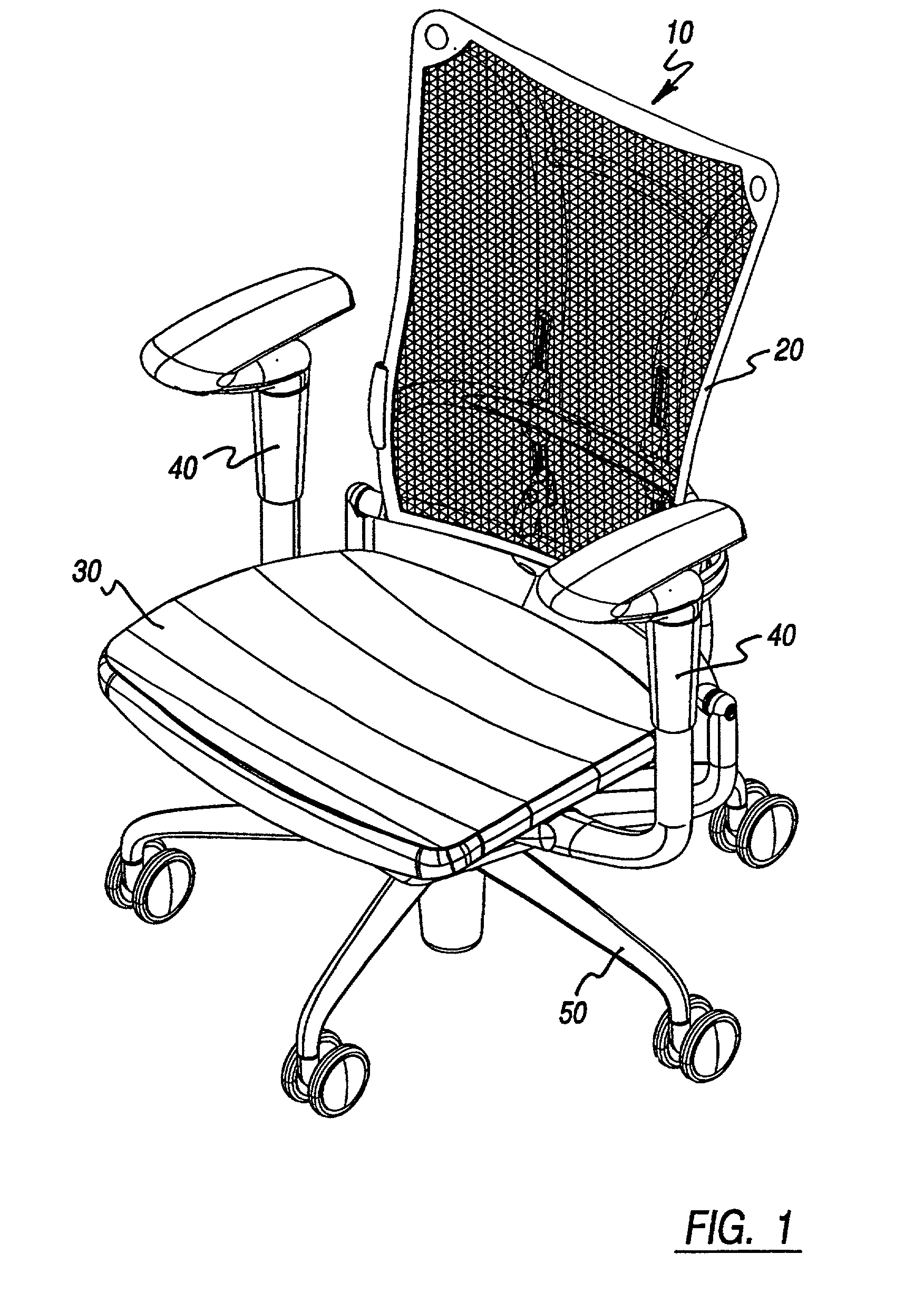
[0009] FIG. 1 is an isometric view of an office chair.
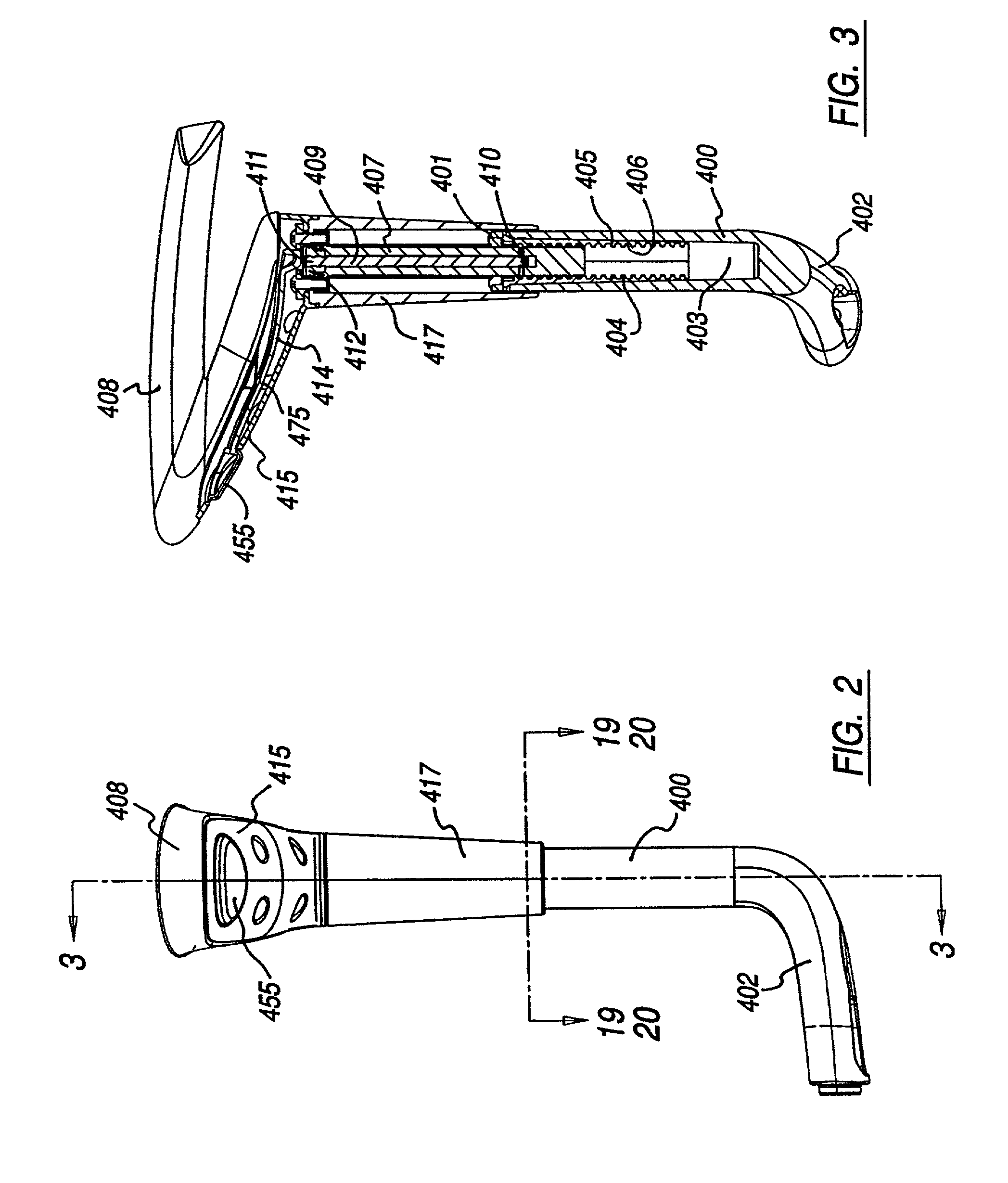
[0010] FIG. 2 is a front elevation view of an armrest assembly.
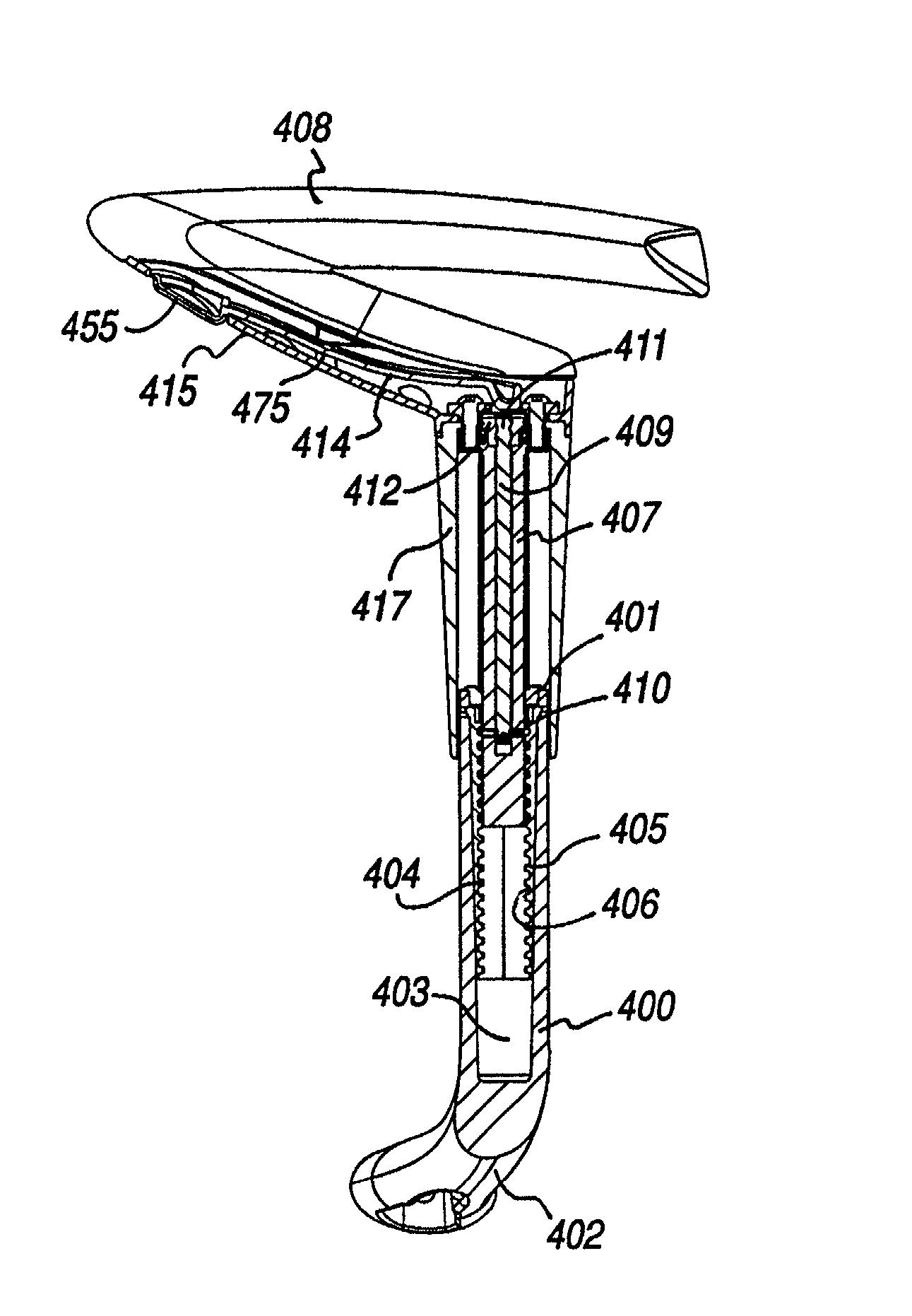
[0011] FIG. 3 is a sectional elevation view taken along line 3-3 of FIG. 2.
[0012] FIG. 4 is an enlarged view of a portion of the view of FIG. 3 showing the armrest assembly in a locked position.

Problems solved by technology

However, such armrests are complicated structurally and / or difficult to use.

Method used


Image

  • Vertically and horizontally adjustable chair armrest
  • Vertically and horizontally adjustable chair armrest
  • Vertically and horizontally adjustable chair armrest

Examples


Embodiment Construction

[0029] While the present invention is open to various modifications and alternative constructions, the preferred embodiment shown in the drawing will be described herein in detail. It is understood, however, that there is no intention to limit the invention to the particular embodiment, form or example disclosed herein. On the contrary, the intention is to cover all modifications, equivalent structures and methods, and alternative constructions falling within the spirit and scope of the invention as expressed in the appended claims, pursuant to Title 35 U.S.C. .sctn. 112 (2.sup.nd paragraph).

[0030] Referring now to FIG. 1, there is illustrated an office chair 10 having a backrest 20, a seat assembly 30, armrest assemblies 40 and a pedestal 50. The disclosure here concentrates on the armrest assemblies which are simply constructed and reliable and allow adjustment both vertically and horizontally.

[0031] Referring now to FIGS. 2 and 3, the armrest assembly 40 generally includes an ups...


PUM


Abstract

A vertically and horizontally adjustable chair armrest is disclosed. The armrest includes an outer shroud, an upstanding support with a central opening and an armrest base. Within the central opening is a guide tube that moves vertically and has oppositely disposed slots. Within the guide tube, but mounted to rotate only, is a rod. At the lower end of the rod is a locking element that extends through the slots in the guide tube. The rod is rotated by a user pivoted lever bearing down on a spring biased activator nut. The nut is keyed to move only in a linear direction but is threaded to engage a mating thread on the rod, thereby causing the rod to rotate. When the locking element is rotated out of engagement with notches in the support opening, the armrest may be adjusted in a vertical direction. Releasing the lever allows the spring to bias the locking element into engagement with the notches to lock the armrest. Horizontal adjustment entails pivoting the armrest from one detent to another within a 45 degree arc.

Description

[0001] The present application is a continuation-in-part of Application Ser. No. 09 / 881,818 entitled "Height And Pivot-Adjustable Chair Arm" and is related to co-pending Application NO. ______ entitled "Improved Ergonomic Chair" (attorney docket 785242) filed on even date herewith and commonly assigned, the disclosures of which are incorporated herein by reference.[0002] 1. Field of the Invention[0003] The present invention relates to an adjustable chair armrest and more particularly to a vertically and horizontally adjustable chair armrest that is simply constructed and easy to use.[0004] 2. Description of the Related Art[0005] Office chairs are frequently adjustable in seat height and armrest height. See for example U.S. Pat. Nos. 5,755,488, 5,765,804 and 5,971,484. Some of these chair armrests are also adjustable horizontally as shown in U.S. Pat. No. 5,641,203. However, such armrests are complicated structurally and / or difficult to use.[0006] What is described here is a vertical...

Claims


Application Information

Patent Timeline
IPC IPC(8): A47C7/54
CPCA47C7/54A47C1/0305A47C1/0308A47C1/03
Inventor PHILLIPS, MATTHEW J.MACHAEL, JAY R.TREGO, BRIAN R.
Owner HNI TECH INC
Learn More