

Connector assembly for a surgical tool
- Summary
- Abstract
- Description
- Claims
- Application Information
AI Technical Summary
Benefits of technology
Problems solved by technology
Method used
Image

Examples
Embodiment Construction
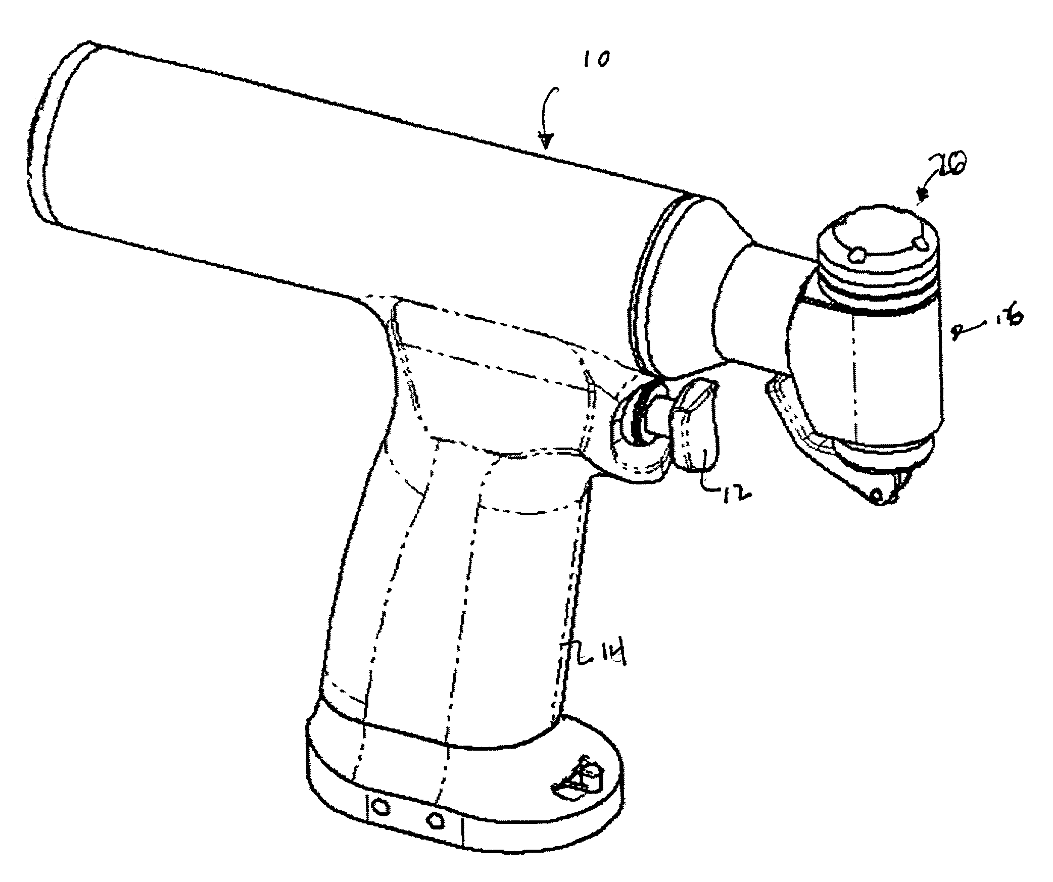
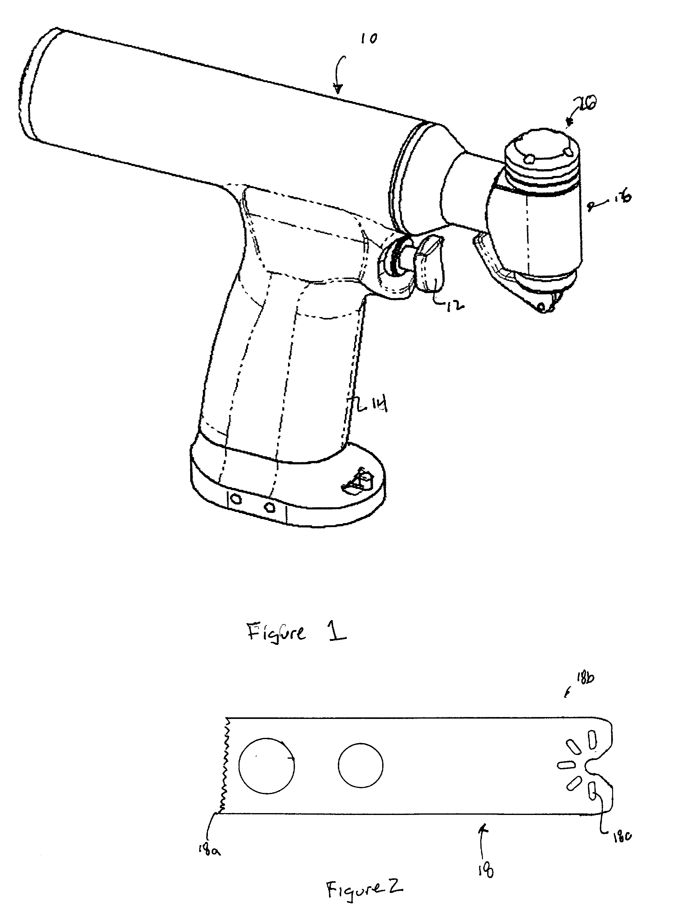
[0028] The present invention is directed to a connector assembly for connecting a surgical saw blade and more particularly a oscillating saw blade to a housing of a surgical instrument. The connector assembly is a keyless system which uses a cam and lever mechanism to securely connect the surgical saw blade including, for example, a sternum saw blade, to the surgical instrument. By using the connector assembly of the present invention, a surgeon or other medical personnel can firmly and securely lock the surgical blade in the connector assembly of the surgical instrument without any special tools, equipment and the like. This enables the surgeon or other medical personnel to easily remove and replace the surgical saw blade during a surgical procedure. The connector assembly of the present invention also allows the surgeon or other medical personnel to apply a high clamping force to the surgical blade with a relatively low actuation force.
Connector Assembly
[0029] Referring now to the...
PUM
 Abstract
Description
Claims
Application Information