High-efficiency air handler

a high-efficiency, air handler technology, applied in the field of air handlers, can solve the problems of large conventional air handlers, high fan static pressures found in larger systems, and large fan energy input of fan energy, and achieve the effect of increasing the energy input of the fan greatly, and reducing the noise of the fan

Inactive Publication Date: 2003-01-02
KOPKO WILLIAM L
View PDF0 Cites 70 Cited by
  • Summary
  • Abstract
  • Description
  • Claims
  • Application Information

AI Technical Summary

Problems solved by technology

There are many problems with large conventional air handlers.
The high fan static pressures found in larger systems require greatly increase fan energy input.
The high pressures also create high fan sound levels, which require the use of expensive and bulky silencers or sound-absorbing ductwork.
The high fan power and high pressures greatly increase the cost of the fans and housings because of higher strength requirements.
While small minisplit or room systems generally do not have these problems, they are not suitable for conditioning large areas.
They generally have a high cost per unit of output.
They also lack any means for distributing air for large distances because they supply air directly to the conditioned space.
One important problem with conventional air handlers is that they are not suitable a new high-efficiency air-conditioning system of the type described in U.S. Pat. No. 6,185,943.
These limitations with conventional air handlers are an outgrowth of a fundamental design philosophy found in conventional air conditioning systems.
In addition the costs associated with reduced productivity of workers because of uncomfortable environmental conditions may be several times these figures, although difficult to quantify.
Conventional approaches to air conditioning have inherent problems that severely limit their efficiency, raise installed cost, and frequently produce poor comfort conditions in the building space.
Solving these problems requires major changes in the basic configuration of air-conditioning systems.
The low supply air temperatures are a result of the need to cool air below its dew point to remove moisture.
There are several important problems with this approach.
Since air flow is through relatively restrictive ductwork, fan static pressures are quite high.
These high static pressures result in large energy use from the fan, which also adds to the cooling load for the rest of the system.
The net result is a very inefficient cooling system.
A second problem is with high compressor energy required.
The low evaporating temperatures create more work for the compressor, which further reduces the efficiency of the system.
A third problem is poor indoor air quality associated with high duct humidity.
In addition water from wet coils wets drain pans and can also wet nearby ductwork.
These wet conditions create a potential breeding grounds for many types of microbes that can cause health and odor problems.
A fourth issue is high noise levels with conventional systems.
The high static pressure creates a need for a powerful fan that usually is quite noisy.
In addition, metal ducts transmit the noise quite well.
Unfortunately these liners increase cost and pressure drop and also can contribute to problems with molds given the high relative humidity in most ducts.
A fifth problem is the potential for drafts with conventional cooling systems.
The low supply air temperatures and high velocities create the possibility of extremely uncomfortable conditions near the vents.
A sixth problem is the need for simultaneous heating and cooling.

Method used


Image

  • High-efficiency air handler
  • High-efficiency air handler
  • High-efficiency air handler

Examples


Embodiment Construction

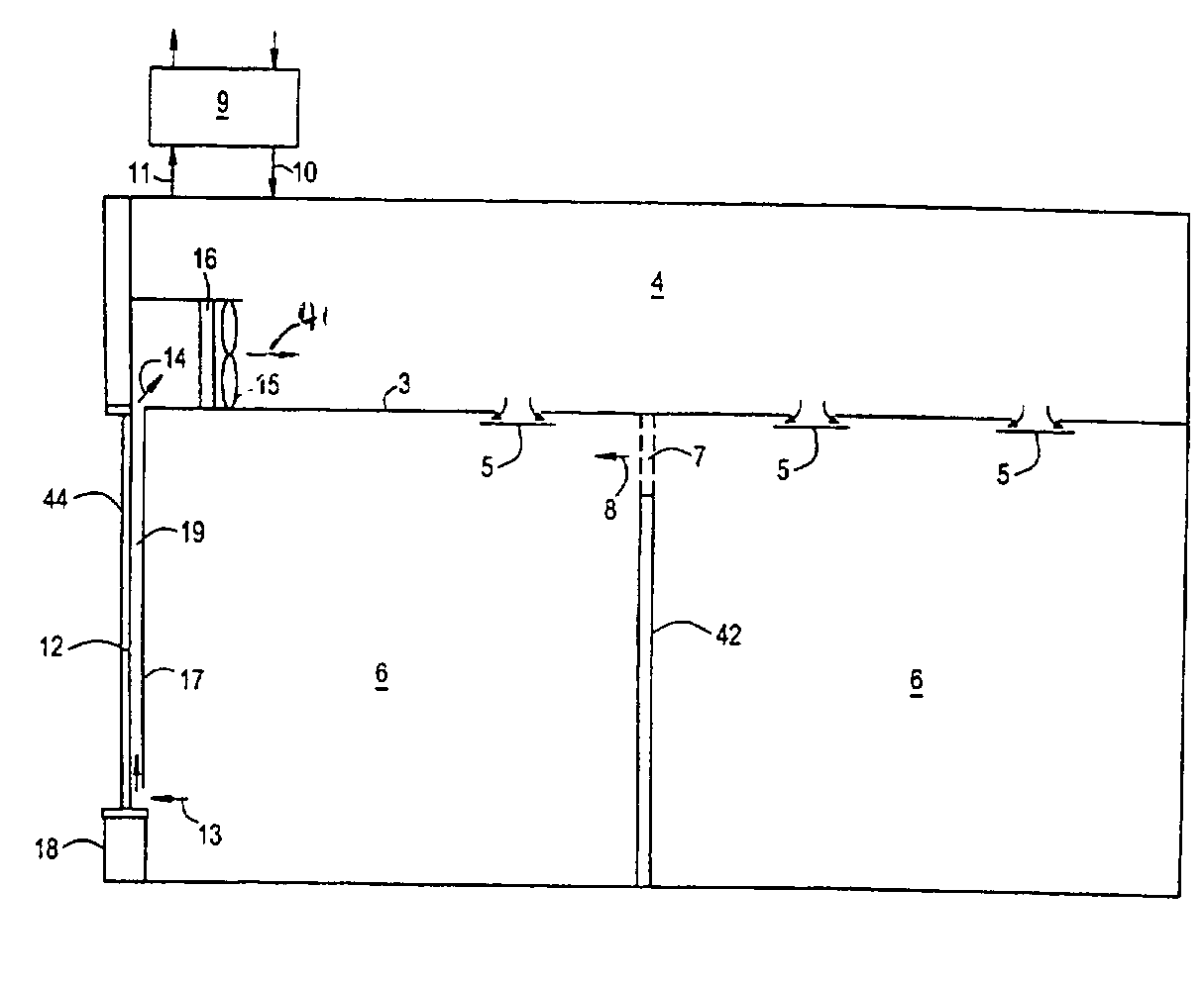
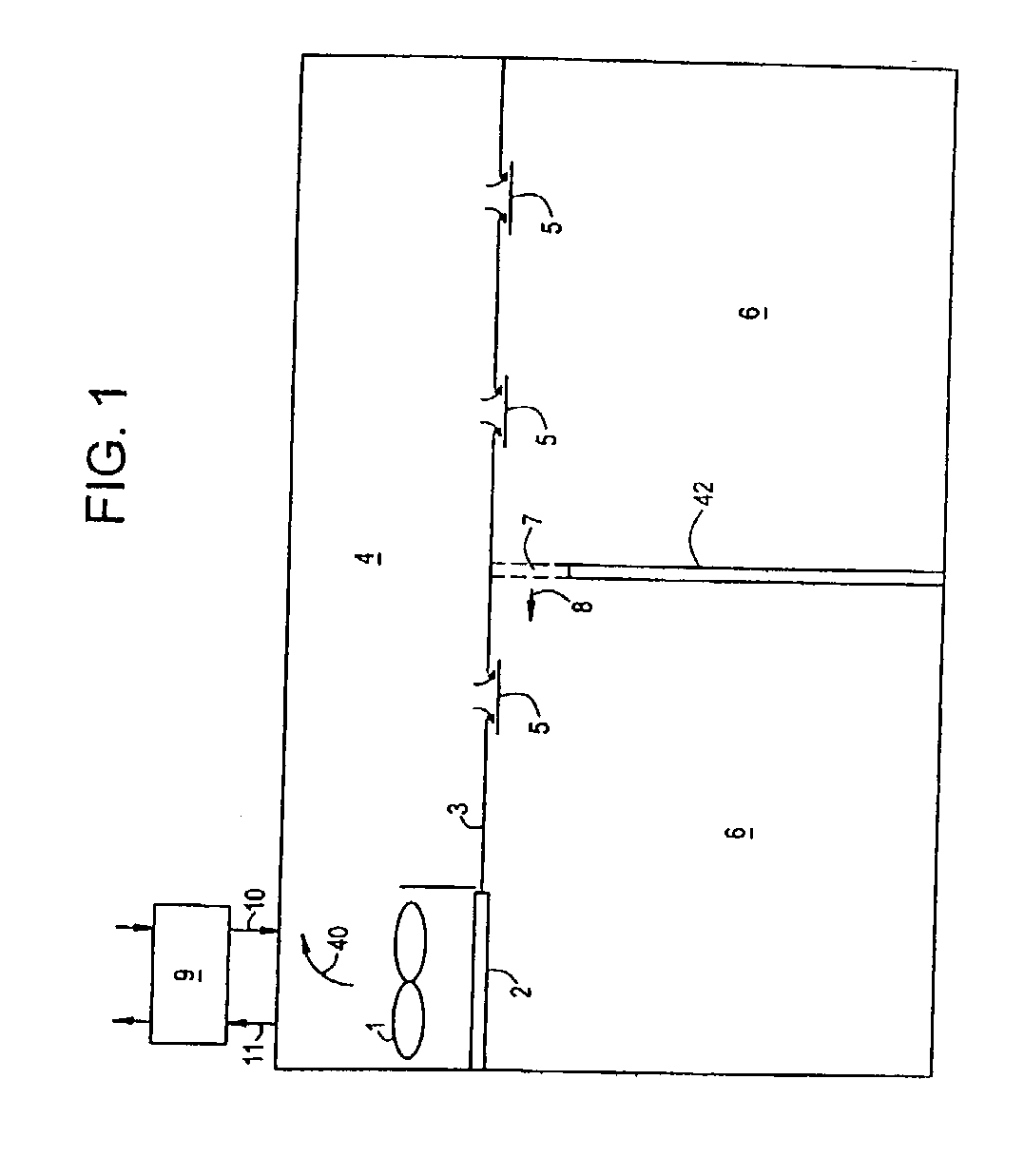
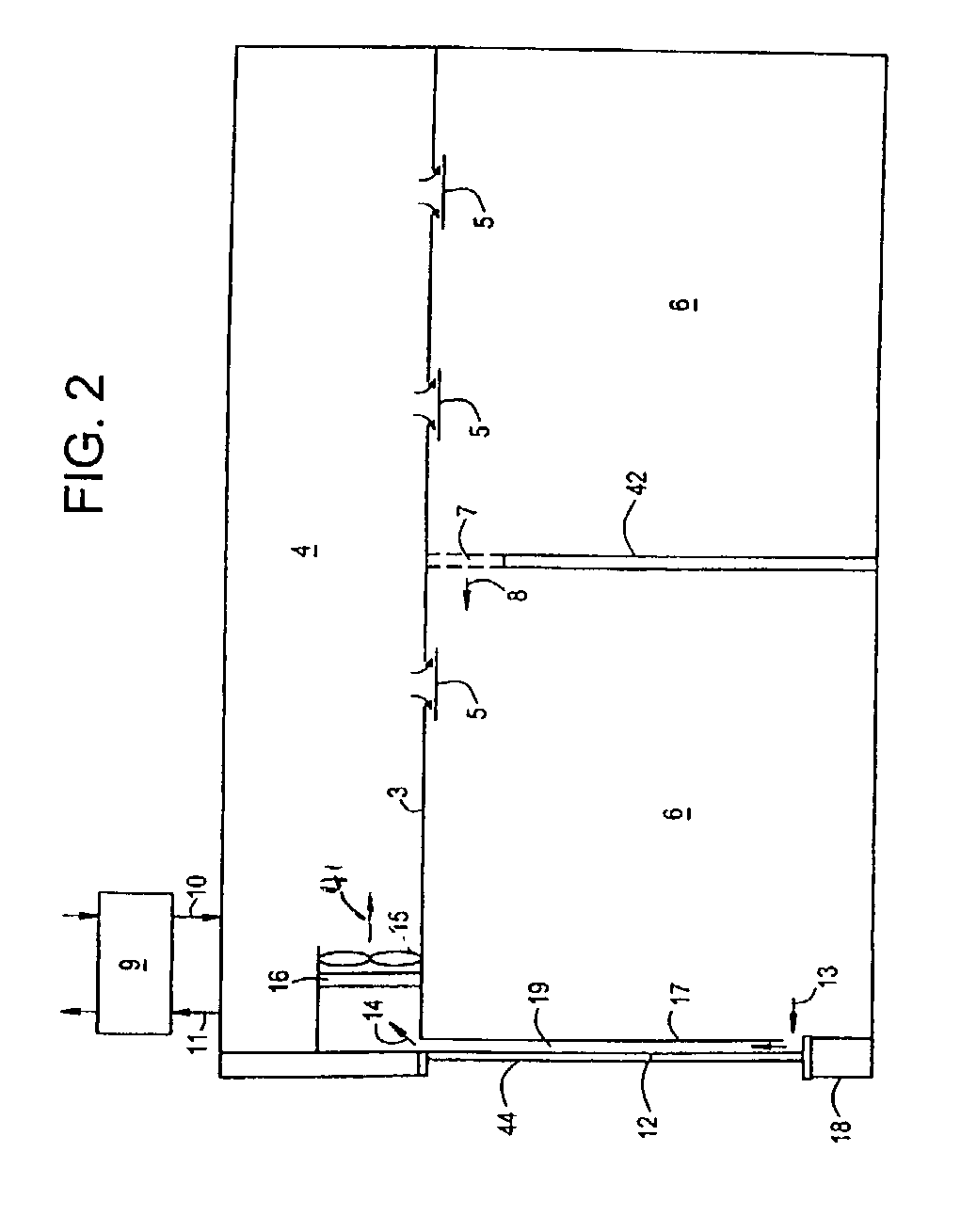
[0032] Preferred system embodiment: FIG. 1 shows a preferred embodiment of the invention. Fan, 1, draws air across coil, 2, where it is cooled or heated to create a supply air stream 40. Ceiling, 3, defines the bottom of a ceiling plenum, 4, that serves as a flow path for air leaving the fan. Vents, 5, provide openings into that allow supply air to mix with air in an occupied portion of the building space, 6. Vent, 7, provides an opening to allow air, 8, to return through a partition 42 in the space. A separate ventilation system, 9, provides dehumidified outside air, 10, to the space and recovers energy from exhaust air, 11.

[0033] The fan may be a propeller or centrifugal fan. It would have to provide only a small static pressure, typically less than 0.2 inches of water. The low static pressures favor the uses of low-speed fans, which should help to reduce fan sound levels and should reduce fan energy use.

[0034] The coil can contain water or brine or a refrigerant. The supply air t...


PUM


Abstract

A high-efficiency air handler that is suitable for moving large volumes of air. The air handler comprises a coil and a fan. The total air volume moving through the unit is preferably over about 2000 CFM, with a total fan static pressure rise of less than about 0.5 inches and preferably less than 0.2 inches of water. The fan is preferably a modified ceiling fan with a rotational speed of less than about 450 rpm. The air handler is preferably part of a system where dehumidification and sensible cooling functions are separate. The separate dehumidification allows for much higher supply air temperatures, preferably within about 10° F. of the space temperature. Low-velocity air distribution through a ceiling plenum or a vent into the space allows for very low fan static pressures, which greatly reduces fan energy use compared to conventional ducted systems. The low static pressures and high supply-air temperatures allow the use of existing drop ceiling construction with little modification. The system can also include low-cost thermal storage. Latent thermal storage is in the form of a concentrated liquid desiccant solution. Chilled water storage is another option. The result is a major improvement in energy efficiency and comfort while reducing installed cost and peak electrical demand of the system.

Description

[0001] This application is a continuation-in-part of application Ser. No. 09 / 772,306 filed on Jan. 29, 2001. Ser. No. 09 / 772,306 is scheduled to issue as U.S. Pat. No. 6,405,543 on Jun. 18, 2002, and is a continuation-in-part of application Ser. No. 09 / 331,758 filed on Jun. 25, 1999, which is now patent U.S. Pat. No. 6,185,943. Applicant claims benefit of a co-pending provisional US application entitled "High-Efficiency Air Handler" filed on Jun. 7, 2002.[0002] 1. Field of Invention[0003] This invention relates to air handlers that are suitable for use in air conditioning systems. Specifically it relates to an improved air handler that is capable of cooling large volumes of air efficiently and quietly that is suitable for use in a high-efficiency cooling system.[0004] 2. Description of Prior Art[0005] Air handlers are commonly used in residential and commercial air conditioning. Air handlers typically comprise a centrifugal blower that moves air over an evaporator or water coil and ...

Claims


Application Information

Patent Timeline
Patent Type & Authority Applications(United States)
IPC IPC(8): F24F1/00F24F3/00
CPCF24F3/00F24F2001/0066F24F2003/144F24F1/00075
Inventor KOPKO, WILLIAM L.
Owner KOPKO WILLIAM L
Why Eureka
Try Eureka