
Ribbed fishtape

a flexible rod and ribbed technology, applied in the direction of lifting devices, electrical cables, electrical equipment, etc., can solve the problems of requiring considerable pulling force, virtually impossible to push through long conduit lengths, etc., and achieves easy grip, high tensile strength, and resist kinking

Inactive Publication Date: 2003-01-02
JAMESON LTD
View PDF0 Cites 0 Cited by
  • Summary
  • Abstract
  • Description
  • Claims
  • Application Information

AI Technical Summary

Benefits of technology

[0006] It is another object of the invention to provide a fishtape which resists kinking.
[0007] It is another object of the invention to provide a fishtape which can be easily gripped.
[0008] It is another object of the invention to provide a fishtape which yields less friction resistance when pushed or pulled through a conduit or passageway.
[0010] These and other objects of the present invention are achieved in the preferred embodiments disclosed below by providing a fishtape adapted for being fed through an internal passageway of a structure, such as a commercial or residential building. The fishtape includes an elongated, flexible rod with a plurality of circumferentially-spaced, longitudinal ribs. The ribs are adapted to promote the fishability of the fishtape through the internal passageway of the structure.
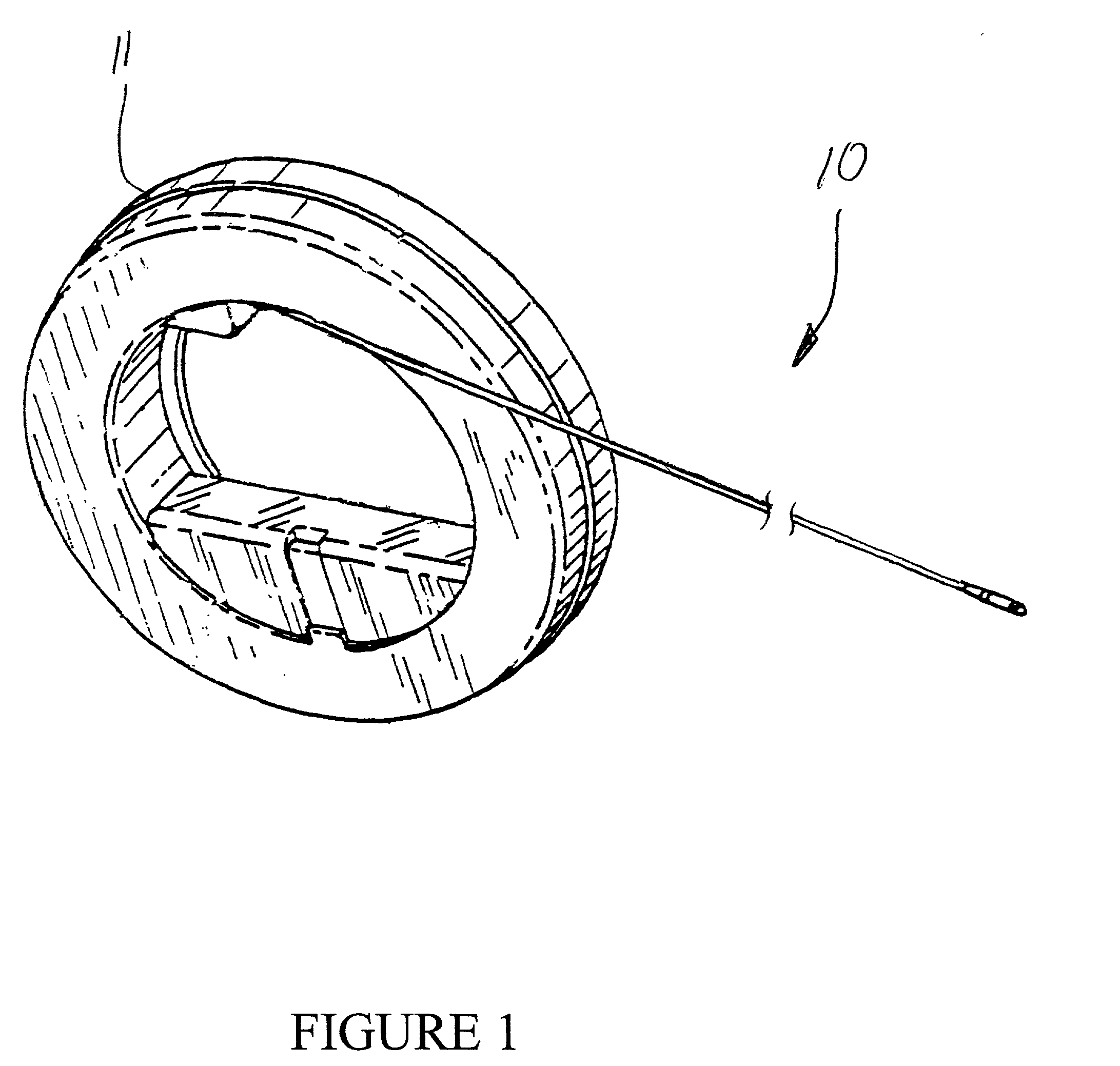
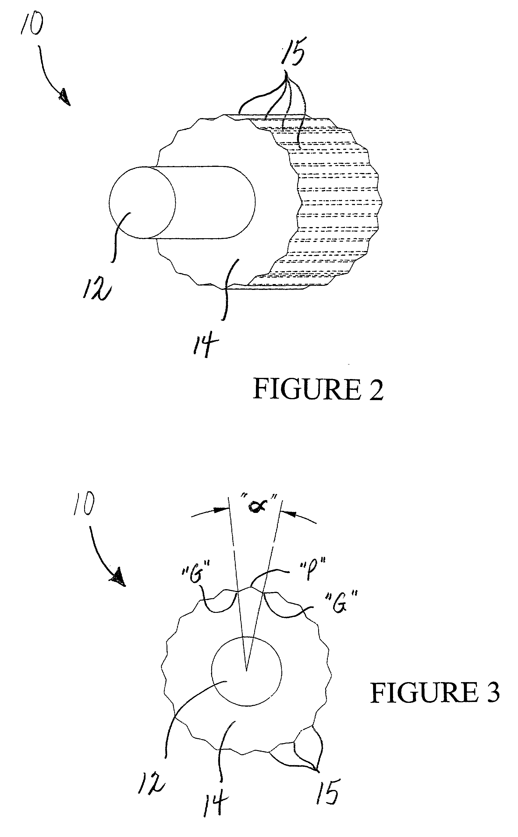
[0026] Referring to FIGS. 2 and 3, the present fishtape 10 includes a fiberglass core 12 and exterior nylon sheath 14. A number of circumferentially-spaced, longitudinal ribs 15 are formed in the sheath 14, and serve to promote fishability of the fishtape 10 through narrow passageways in buildings and other structures. The longitudinal ribs 15 enhance the column strength and overall stiffness of the fishtape 10. As best shown in FIG. 3, each rib 15 is defined by a point "P" with grooves "G" formed on opposite sides of the point. The ribs 15 create a reduced area of contact between the fishtape 10 and structure of the passageway, thereby reducing the effect of friction and requiring less tensile force to pull the fishtape 10 back through the passageway. In addition, the grooves "G" provide spaces for lubricants which may be applied to the fishtape 10 to further reduce friction.
[0028] A process for forming the fishtape is illustrated generally in FIG. 4. Nylon pellets are fed into a hopper 21, heated, and moved downstream through the extruder 22 to a forming die 24. A spooled length of fiberglass rod 25 forming the core 12 of the fishtape 10 passes from spool 26 through the forming die 24 together with the heated nylon forming the outer sheath 14 of the fishtape 10. The die 24 has a toothed cross-section which forms longitudinal ribs 15 in the nylon sheath 14 as the fishtape 10 exits the extruder 22. Preferably, the nylon is heated in the extruder 22 to a temperature of approximately 550 degrees F. When applied to the fiberglass rod 25 at the forming die 24, the heated nylon causes the outer coating of the fiberglass rod 25 to melt away, thus creating an increased bond between the nylon sheath 14 and fiberglass core 12. The increased bond reduces the potential for movement of the fiberglass core 12 within the outer sheath 14. As a result, the fishtape 10 is capable of achieving a smaller bend radius without failure. Moreover, the synergistic combination of nylon and fiberglass during extrusion creates a fishtape 10 with a higher flex strength and abrasion resistance.

Problems solved by technology

Because most electrical wire and cable is relatively thin and flexible, pushing it through long lengths of conduit is virtually impossible.
Overcoming this resistance generally requires considerable pulling force.

Method used


Image

  • Ribbed fishtape
  • Ribbed fishtape
  • Ribbed fishtape

Examples


Embodiment Construction

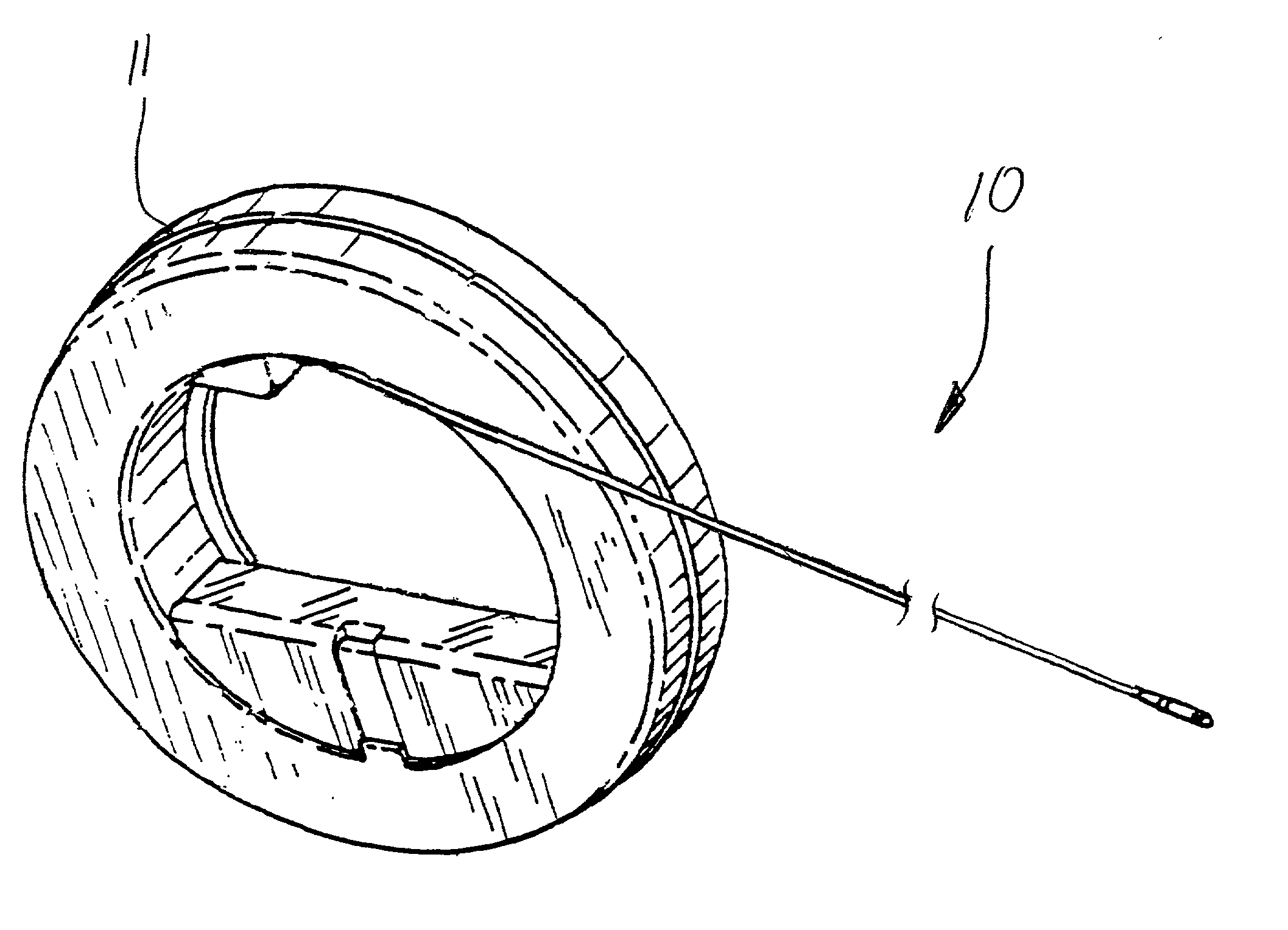
[0025] Referring now specifically to the drawings, a fishtape according to the present invention is illustrated in FIG. 1 and shown generally at reference numeral 10. Fishtape 10 is commonly supplied in a reel, such as reel 11, containing 50 or more feet of tape. Examples of fishtape reels are provided in applicant's prior issued patents, U.S. Pat. Nos. 5,106,056 and 5,340,084. The complete disclosure of these patents is incorporated herein by reference.

[0026] Referring to FIGS. 2 and 3, the present fishtape 10 includes a fiberglass core 12 and exterior nylon sheath 14. A number of circumferentially-spaced, longitudinal ribs 15 are formed in the sheath 14, and serve to promote fishability of the fishtape 10 through narrow passageways in buildings and other structures. The longitudinal ribs 15 enhance the column strength and overall stiffness of the fishtape 10. As best shown in FIG. 3, each rib 15 is defined by a point "P" with grooves "G" formed on opposite sides of the point. The ...


PUM


Abstract

A fishtape is adapted for being fed through an internal passageway of a structure. The fishtape includes an elongated, flexible rod with a plurality of circumferentially-spaced, longitudinal ribs. The ribs are adapted to promote the fishability of the fishtape through the internal passageway of the structure.

Description

TECHNICAL FIELD AND BACKGROUND OF THE INVENTION[0001] This invention relates to an elongated, nonconductive flexible rod commonly used by electricians and telephone or communications installers and technicians, and referred to in the art as "fishtape". Fishtape is typically used to facilitate installation of wire and cable through conduit or other passageway in walls, ceilings, and floors of buildings. Standard fishtapes are made of 0.080" to 0.500" diameter fiberglass or extruded plastic, and are supplied in reels containing 50 or more feet of tape.[0002] Because most electrical wire and cable is relatively thin and flexible, pushing it through long lengths of conduit is virtually impossible. To facilitate running wire and cable using fishtape, a length of fishtape is first fed through the conduit from one open end to the other. The wire or cable is then attached to a leading end of the fishtape, and the fishtape pulled back through the conduit with the attached wire or cable trail...

Claims


Application Information

Patent Timeline
Patent Type & Authority Applications(United States)
IPC IPC(8): H02G1/08
CPCH02G1/083H02G1/085
Inventor POOLE, WILLIAM K.
Owner JAMESON LTD
Learn More